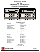
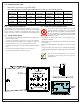
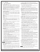
Reference Guide for the DS7080iP-32 Two Partition Control/Communicator Armed Ready To Arm Status Power Fire Armed Perimeter Status Power Supervisory Bell Silenced Fire Trouble 1 2 3 4 5 6 7 8 On On 1 2 3 Off 1 2 3 Off 4 5 6 Perimeter Only 4 5 6 Perimeter Only 7 8 9 No Entry 7 8 9 No Entry * 0 # Bypass * 0 # Bypass System Reset DS7447 System Reset DS7445 Keypad Quick Reference Guide Turning On (Arming) your System [PIN] + [On] Normal Arming [PIN] + [No Entry] [
Table of Contents 1.0 Specifications ............................................................ 4 1.1 1.2 1.3 Enclosure Housing ............................................................. 4 Temperature ....................................................................... 4 Power ................................................................................. 4 1.3.1 1.4 1.5 1.6 1.6.1 1.6.2 1.7 1.8 1.9 1.10 1.11 1.12 Accessory Power ......................................................
9.47 Address 121 - Point Expansion Module Fault Report ......... 40 9.48 Address 122 - Point Expansion Module Fault Restoral Report 40 9.49 Address 123 - Octal Relay Control and Reports ............... 40 9.50 Address 124 - Default Programming ................................. 41 10.0 Installation Guide for UL Listed Systems ............. 42 10.1 DS7080iP-32 UL Listings: ................................................. 42 10.2 Installation Considerations ................................................
1.0 Specifications 1.1 Enclosure Housing 1.6 1.6.1 DS7443 Keypad The standard enclosure is manufactured from 20 Ga., cold-rolled steel, and measures 12.5 in. Wide, by 14.5 in. High, by 3 in. Deep (31.8 cm W x 36.8 cm H x 7.6 cm D). A keyed lock is included, and this enclosure has a provision for an optional tamper switch (required for Commercial Burglary applications) for monitoring the door. 1.
1.12 Standby Current Load Battery AH - (20% Storage + 0.375 AH’s Alarm) The following table is the derated battery divided by hours minus the control standby (150 mA): Rechargeable Battery Size 4 AH 7 AH 8 AH 14 AH 15 AH 17.2 AH 2.0 Derated 2.825 5.225 6.025 10.825 11.625 13.385 AH AH AH AH AH AH Max. Standby Max. Standby Max. Standby Max. Standby Max. Standby for 8 hours for 24 hours for 48 hours for 60 hours for 4 hours 590 mA 230 mA X X X X 1.0 A 530 mA 100 mA X X X 1.0 A 640 mA 130 mA 1.
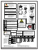
3.0 Control Terminal Wiring WARNING Before servicing this equipment, remove all power including the transformer and battery. Also remove the phone line connection. TYPICAL BURGLAR AND FIRE WIRING Zone Input Ground Zone 1 Only Zone 1 Only 14 14 This System is Power Limited except for the Battery terminals. All wiring entering this enclosure must be Power Limited. CAUTION: Incorrect connections may result in damage to the unit.
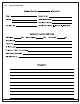
4.0 System Worksheet DS7080iP-32 Reference Guide Copyright © 2001 Detection Systems, Inc.
4.0 Page 8 System Worksheet (continued) P/N 39818D Copyright © 2001 Detection Systems, Inc.
5.0 System Overview • Description: The DS7080iP-32 Control/Communicator is a fully integrated hard-wire security and residential fire alarm system. - It can support up to 8 input zones, two partitions, 24 individual users, and multiple output options. - Up to 4 keypads may be used to provide user interface with the system, as well as programming access for the installer. • Zone: A zone is an input to the DS7080iP-32 Control/ Communicator. There are 8 hard-wired zones on the main circuit board.
6.0 6.1 - This zone is bypassed when arming only the perimeter. Glossary Zone Programming • Invisible Alarms: This is a zone programmed not to have an alarm output or an alarm display (except when arming) at any keypad when activated. Invisible Alarm zones are recommended for holdup alarms. An alarm signal will be sent, but the keypad display will not indicate an alarm while this zone is violated.
• Interior Delay: This interior zone follows Entry Delay Time #1. • Perimeter Homeguard: This zone type is active when the panel is armed. When the panel is armed perimeter only, this is a delayed zone. When armed full, this is an instant zone. The Perimeter Homeguard follows Entry Delay Time #1. • Perimeter Follower Homeguard: These zones are always delayed when the panel is armed in the perimeter only mode.
• Siren on Comm. Failure for Silent Zone: If programmed, a silent zone will sound the alarm outputs if the zone is in an alarm condition and the system fails to communicate with the central station. 6.6 Emergency Key Programming • Restore when Sounders Silence: If programmed, a zone sends a restoral report and is ready to activate again only after the burglary bell cut-off time expires or the bells are silenced. - The zone can alarm multiple times per armed period.
6.10 Phone Number General Control Programming 6.13 Force Arming Programming • Enable Remote Programmer Callback: If programmed, when the remote programmer tries to initiate a session with the panel, the panel will hang up and call the remote programmer phone number. - This ensures the correct remote programmer is initiating the call. • Dial Pulse on all Phone Numbers: If programmed, the panel will dial to phone number 1, 2, and the remote programmer phone number 3 using the pulse format.
• Open: This report is sent when the system has been disarmed. In SIA or Contact ID formats, the user number for the person who disarmed the system will be sent with this report. To send the user number along with an Open report in other formats, program the extended digit of the report as *5. The Open report will only be sent if a Close report was sent previously. • Close: This report is sent when the system has been armed.
6.16 FCC Compliance Notice 6.18 Canadian Dept. of Communications This equipment has been tested and found to comply with the limits for a Class B digital device, pursuant to Part 15 of the FCC Rules. These limits are designed to provide reasonable protection against harmful interference in a residential installation.
7.0 7.1 7.1.3 Installation Considerations Operating Guide Proper location of detection devices is one of the most critical factors in a fire alarm system. Fire Safety This fire alarm system can provide early warning of a developing fire. Such a system, however, does not ensure protection against property damage or loss of life resulting from a fire. Any fire alarm system may fail to warn for any number of reasons (e.g. smoke not reaching a detector that is behind a closed door).
7.2 Setting the Date It is recommended that this procedure be performed at a DS7447 Keypad. No visual clues will be given from a DS7445 keypad. Steps to Change the Date # 1. # 2. # 3. Enter the Master Code Programming Mode Command Sequence # 5. Enter the Day Enter the Year (display will scroll to this) “Enter Month” [2] (01 … 12) [0] [1] through [1] [2] January # 4.
7.4 Attempting to assign the same PIN to multiple User Numbers will result in the three-beep error tone, and the change will not be made. Personal Identification Numbers 7.4.1 General Information • PIN: Personal Identification Number. This is the 4- or 6-digit code (determined in Address 003) users enter at the keypad to gain access to the system. A PIN may be assigned to each User Number 001 - 024. • Partition (Area): This is the area the User has authority in.
7.5 Automatic Arming To inform occupants that the system is about to arm, a pre-arming period will begin 15 minutes before the system arms automatically. If programmed by the installing company, the keypad sounders, and any outputs programmed to follow the keypad sounders, will pulse five times every minute. During the last five minutes before arming, these sounders will be on steady. Once per minute the DS7447 keypad will read, “Arm in nn min./PIN + OFF - extend.
7.7 Error Displays Control panel problems are indicated by a flashing green Power Light. The DS7447 display will also read “Control Trouble, Enter [#] [8] [7].” The DS7445 will only flash the green Power Light. The Error messages may only be read when the control is disarmed. Contact your installing company if the problems persist. 1. DS7447 - “AC Power Failure”: DS7445 - LED 1 turns on steady: There is a power failure and the panel is operating on backup battery. 2.
7.9 Zone Test This chart explains the procedure for performing a Zone Test. It is recommended that the system be tested weekly. The Zone Test is used to confirm that detectors will report alarms. Zone Test works on all zones, except 24-hour zones and fire zones. While the keypad is in Zone Test, no control panel alarms will activate an alarm, except 24-hour zone alarms and fire alarms. These will override the Zone Test function.
7.11 Communicator Test This chart explains the procedure for performing a Communicator Test. This test is available only if your system transmits alarms and system information to a monitoring service, and has been programmed by the security installing company to permit communicator tests. A long beep will initially sound to acknowledge the start of the test. If the test is successful, the sounder will again issue one long beep. If the test fails, the keypad sounder will turn ON continuously.
8.0 How to Program the DS7080iP-32 To enter the programming mode, the panel must be disarmed. When in the programming mode the control is disabled and no alarms will be processed, including 24-hour zones and fire zones. To enter the Programmer’s Mode, enter the [Programmer’s Code] followed by [#] [0]. Shorting the programming pads (see Section 2.2 for location) on the control panel will also activate the Programmer’s Mode. The default Programmer’s Code is 9876. Enter the Program Address (i.e.
9.1 Address 001 - EX8 Zone Expansion Module Control This Address determines how many EX8 Zone Expansion Modules are in the system and the zone response time for those zones. There are 8 hard-wired zones on each Zone Expansion Module. The modules need to be enabled in ascending order from Module 1 to Module 3. Programming the EX8 Expansion Module: • Module 1 is fixed at Option Bus Address 101 and makes zones 9 through 16 available to the system.
9.3 Address 003 - User Controls User Controls are used to determine if there is a keypad audible during the exit time, if the audible devices are tested upon arming the system, whether the Trouble Zone is Normally Open or Closed and if the PIN numbers are 4 or 6 digits in length. • Keypad Audible During Exit will activate the keypad sounder (and any outputs programmed to follow the keypad sounder) once every 5 seconds during the exit delay. At 10 and 5 seconds remaining, the sounder will activate 3 times.
9.7 Address 007 - Keypad Assignment This selection is used to determine if a keypad is Alpha (LCD) or LED. Each keypad slot is assigned an Option Bus Address of 1, 2, 3 or 4 respectively. 9.8 Address 008 - Language and Arming Controls This address is used to determine the following: • Display Language: This selection is used to determine if system messages are displayed in English or another language. Selections for other languages will vary, depending on the model ordered.
9.10 Address 010 - Time Delays This address is used to determine the entry and exit delays as well as the bell cutoff times. If a bell cutoff time is programmed with the maximum value of 099, then the actual cutoff time will be 30 seconds.. 9.11 Address 011 - Report Controls Address 011 is used to determine report routing. Use options 0-3 for Non-partitioned systems. Do not select Options “4” through “C” if “No Partitioning” is selected in Address 002 Digit 6.
9.
9.15 Address 015 - Phone # 1 Format 9.16 Address 016 - Phone # 2 Format DS7080iP-32 Reference Guide Copyright © 2001 Detection Systems, Inc.
9.
9.20 Address 025 - Auto Test / Remote Programmer Call-Out Time If “Send a Test report every hour” was selected in Address 024, setting the “Auto Test Call-Out Hour/Minute will have no affect on the call out time. The hourly Auto Test will occur within a few minutes after the start of each hour as defined by the panel’s date and time set in the master user menu. This feature requires the panel’s date and time to be set. 9.
9.24 Addess 029 - Keypad Reports Keypad Reports are programmed for the value you wish to send to the central station when the emergency keys are pressed. DEFAULT Two Digits, 00 through FF 00 00 00 00 00 00 KEYPAD FIRE REPORT KEYPAD FIRE RESTORAL REPORT KEYPAD EMERGENCY ALARM REPORT KEYPAD PANIC ALARM REPORT KEYPAD TAMPER REPORT KEYPAD TAMPER RESTORAL REPORT 9.25 Address 030, 031, 032, 033 - Zone Type • Disabled: These zones are not monitored, and will not generate alarm or trouble conditions.
• Entry/Exit Delay #1: A delayed zone is ignored during the programmed times immediately following arming during the exit delay. If the zone is faulted while the control is armed and not in exit delay then an entry delay cycle will be started, and a continuous entry tone will be sounded at the keypads. If the control is not disarmed by the end of the entry delay, an alarm will result. There are no keypad tones during the exit delay unless the feature “Keypad Audible During Exit Delay” is selected.
• Interior Delay: This interior zone follows Entry Delay Time #1 (Address 010) during normal arming. When arming using the “No Entry” button, this zone becomes an interior instant. • Perimeter Homeguard: This zone type is active when the panel is armed. When the panel is armed perimeter only, this acts like an Entry/Exit Delay #1. When armed full, this is an instant zone. • Perimeter Follower Homeguard: These zones act like an Entry/Exit Delay #1 zone when the panel is armed in the perimeter only mode.
9.28 Address 042, 043, 044, 045 - Zone Bypass This determines whether the user can bypass the zone. Zones programmed for bypassing can be bypassed even when in alarm. Fire zones will not be bypassable, even if programmed as bypass allowed. 0 = No Bypassing Allowed 1 = Bypassing Allowed (Default) 9.29 Address 046, 047, 048, 049 - Custom Arming Custom Arming Programming allows the [#] [4] key sequence on the keypad to be used for custom arming.
REPORTS If a value of 00 is programmed in any of these locations the panel will not send that particular report. • Pulsed Formats (3/1, 3/1E, 3/1 with Parity, 3/1E with Parity, 4/1, 4/2 and BFSK) will need a unique value placed at each address location. The digits that is furthest to the left in each location is the primary reporting digit. As a recommendation for the pulsed formats, the table in Section 11.3 “Suggested Values” gives a baseline from which to program the various addresses.
9.33 Addresses 062, 063, 064, 065 - Zone Trouble Reports Two Digits, 00 through FF 9.34 Addresses 066, 067, 068, 069 - Trouble Restoral Reports Two Digits, 00 through FF 9.35 Addresses 070, 071, 072, 073 - Zone Bypass Reports Two Digits, 00 through FF 9.36 Addresses 074, 075, 076, 077 - Bypass Restoral Reports Two Digits, 00 through FF DS7080iP-32 Reference Guide Copyright © 2001 Detection Systems, Inc.
9.37 Address 078 - Open/Close Reports 9.38 Address 079 - AC/Battery Reports 9.39 Address 080 - Remote/Local Programming Reports 9.40 Address 081 - Exit Error, Recent Closing, System Trouble, System Trouble Restoral Reports 9.41 Address 082 - Test Reports Page 38 P/N 39818D Copyright © 2001 Detection Systems, Inc.
9.
9.45 Address 119 - Point Expansion Module Tamper Report 9.46 Address 120 - Point Expansion Module Tamper Restoral Report 9.47 Address 121 - Point Expansion Module Fault Report 9.48 Address 122 - Point Expansion Module Fault Restoral Report 9.49 Address 123 - Octal Relay Control and Reports Page 40 P/N 39818D Copyright © 2001 Detection Systems, Inc.
9.50 Address 124 - Default Programming Defaulting the control panel will result in the loss of all custom programming. This includes Zone programming, Report programming, Keypad programming (only the keypad set as Option Bus Address 1 will function), Alpha programming, Telephone numbers and Account codes. If the digit 1 is entered into Address 124 all programming information will be lost and cannot be recovered. DS7080iP-32 Reference Guide Copyright © 2001 Detection Systems, Inc.
10.0 Installation Guide for UL Listed Systems 10.
10.2.1 Special Requirements for Partitioned Systems • The control unit and burglar alarm signal are intended to be installed in one premesis, under one management, one ownership and one address which is then partitioned. D. Alarm Output Programming: • Alar m Output (Program Address 009 digit 1) must be programmed as *0 (A). E. General Control Programming: • The indicating device (bell) must be placed where it can be heard by all partitions.
• AC Failure Report (Program Address 079, digits 5 & 6) must be programmed. • Open Report (Program Addresses 011, digit 1, and 078, digits 1 & 2) must be programmed. • Close Report (Program Addresses 011, digit 1, and 078, digits 3 & 4) must be programmed. • 24-Hour Check-In Reports (Program Addresses 082, digits 1-4 and 024, all digits) must be programmed. 2. Timer Programming: • Bell Cutoff Times (Program Address 010, digits 10-15) must be programmed for not less than 15 minutes.
10.3.5 Central Station Burglary Alarm The control must be installed in accordance with UL Standards UL611 and UL681 for all grades of service. A. Grades AA and A Installations using the Applied Spectrum PAL200 and the DACT Required Accessories: • The control must be installed in a Detection Systems’ model AE7080CC enclosure with a cover actuated tamper switch installed. • The Applied Spectrum PAL200.
• Program Address 008, digit 2, must be programmed for the Commercial mode (digit 2 = 0). 4. Zone Programming: • The Burglar alarm output signal (whether pulsed or steady) must be different from the Fire alarm signal. 5. Alarm Output Programming: • Alarm Output, Program Address 009, digit 1 must be programmed as *0 (A). 10.4 Using the Ademco AB-12 Bell/Housing 1) Disconnect the wire jumper from Terminal 4 to the inner housing of the Bell Box.
11.0 Report Programming Suggested Values 11.1 Personal Dialing and Pager Format This is a 2 pulse per second (PPS) 0/2 (no account code/2 report event digits) format intended for manual reception, i.e. the panel will call a phone number where a person is expected to answer. After a call is made, the panel will start sending the first report.
Personal Dialing and Pager Format (suggested values) 4/2 Format (suggested values) Page 48 P/N 39818D Copyright © 2001 Detection Systems, Inc.
11.3 Suggested Values for BFSK and other Pulse Formats For Additional Information, see Programming Addresses 054-082 and 117-123. DS7080iP-32 Reference Guide Copyright © 2001 Detection Systems, Inc.
12.0 Report Programming Values Sent 12.1 SIA Format SIA reporting allows the installer to select the type of event each report will send to the central station. For example, if a burglary zone is used as a 24 hour panic zone, it can now report as a PA (panic alarm) when using the SIA format. The event type is programmed in the extended digit of the report (Addresses 054082 and 117-123). To activate a report when using the SIA format, place a “1” in the first reporting digit.
12.2 Contact ID Format Values Sent For Additional Information, see Programming Addresses 054-082 and 117-123. DS7080iP-32 Reference Guide Copyright © 2001 Detection Systems, Inc.
12.3 High Speed 4/9 Format For Additional Information, see Programming Addresses 054-082 and 117-123. Page 52 P/N 39818D Copyright © 2001 Detection Systems, Inc.
12.3 High Speed 4/9 Format (continued) DS7080iP-32 Reference Guide Copyright © 2001 Detection Systems, Inc.
13.0 Programming Addresses Address Address 50/60 Hz .................................................................................................. 002 AC Failure Report ................................................................................... 079 AC Failure Report Delay ......................................................................... 026 AC Failure Restoral ................................................................................. 079 Alarm Bell Cutoff .......................
14.0 Troubleshooting Guide #87 Display “AC Power Failure” 1. Not enough AC voltage or current load too great for transformer. 1. Make sure proper transformer is used (see AC Input note in Section 3.0). 2. AC not present. 2. Make sure panel is not connected to a switched outlet that has been turned off. 3. Blown transformer fuse. Replace transformer. 4. Load too great for transformer. Place meter on AC scale and select the correct setting for A or mA.
#87 Displays “Communicator Err” Automatic Test report not sent. 1. Ground Star t phone line. (Normal operation referred to as loop start) 1. Requires phone line to short to ground to access dial tone. See address 009. See Section 6.2 Ground Start Timer for connection and explanation on ground start lines. 2. PBX phone system PBX: where a number needs to be dialed to get dial tone. Example: dial (9) followed by phone number. 2. Check Address 012. Should be programmed as “Dial Tone on all phone numbers”.
#87 Displays “System Fault” “Trouble Zone Fault” sounder not on and keypad operating fine. 1. Trouble zone activated. With all power removed and after you have grounded yourself, visually check EEPROM for bent or misaligned pins. 1. Check Trouble zone wiring. 2. Check programming in Address 008. This is an unsupervised connection and should only be used as a trouble indication for tamper devices. Differs from actual zone trouble. Keypad blank. AC and battery power is good. 2. Keypad wiring fault 1.
Index Symbols 24-Hour Zone 10, 32 3/1 36 3/1 with Parity 36 3/1E 36 3/1E with Parity 36 4/1 36 4/2 36 4/9 Format 52 60Hz/50Hz 24 A A Key 12 AC Failure Report 14 AC Failure Restoral Report 14 AC Power Failure 20 AC Report Delay 31 AC/Battery Reports 38 Access Control 1 Access Output 11 Access PIN 18 Account Codes 28 Ademco AB-12 Bell/Housing 46 Alarm, Invisible 10 Alarm, Keypad Emergency 13 Alarm, Keypad Fire 13 Alarm on Open 10 Alarm on Short 10 Alarm, Silent 10 Allow All Arming Levels 24 Allow Swinger Shu
Partitioning 24 Perimeter Arming 1, 11 Perimeter Follower Homeguard 11 Perimeter Follower Homeguard Zone 34 Perimeter Homeguard 11 Perimeter Homeguard Zone 34 Perimeter Instant 10 Perimeter Instant Arming 11 Perimeter Instant Zone 32 Personal Identification Numbers 18 Phone # 1 Format 29 Phone # 2 Format 29 Phone Answering Programming 13 Phone Controls 28 Phone Numbers 30 PIN 18 PIN Authority Levels 18 Point Expansion Module Fault Report 14, 40 Point Expansion Module Fault Restoral Report 14, 40 Point Expan
Detection Systems, Inc. 130 Perinton Parkway Fairport, New York, USA 14450-9199 (585) 223-4060 • (888) 289-0096 • Fax: (585) 223-9180 Copyright © 2001 Detection Systems, Inc.