Operating Instructions Only for Authorized Service Technicians Brine-Water and Water-Water Heat Pumps AQUATOP TC 02/2008 Art. No.
Table of Contents Table of Contents Basic Information Installation and Connection Instructions Electrical Connection Assembly Charging Geothermal Heating Systems Initial Startup Troubleshooting System Equipment Dimensions Technical Data Initial Startup Log Notes 2 …………………………………………………....... Safety Information…………………….................. General Info................................................ ....... Legal Guidelines, Rules...................................... Warranty Terms......................
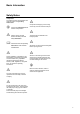
Basic Information Safety Notes Safety Notes The following notes and information are generally used in the operating instructions: L E Comply with information about function and operation. E Components and piping of the cooling circuit may never be used for transport. E Always comply with and observe all safety notes and safety information. Information about the operating instructions of the controller LOGON B WP The heat pump is fastened to the transport pallet.
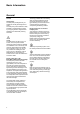
Basic Information General General Usage Range The heat pump is designed only for heating as well as generating service water. The heat pump can be utilized in newly installed or existing heating systems by complying with the usage limits as defined by the AQUATOP planning document. E Setup The heat pumps can be set up on a smooth, level, and plane surface without the need of a base or pedestal. The installation room must be dry and frost-free. Rooms with much humidity such as laundry rooms, etc.
Basic Information Legal Guidelines, Rules, Warranty Terms, Receiving Inspection General Information These operating instructions serve the correct installation, adjustment, and maintenance of the equipment. The following information must therefore be read carefully and the heat pump must be installed, inspected, and maintained by correspondingly trained technicians. The manufacturer is not liable for mechanical, hydraulic, or electrical modifications after the warranty expires.
Installation and Connection Instructions Delivery Scope The following components are included with the heat pump: 1 2 3 4 5 6 7 8 9 Preattached tubes in rear of unit 1 2 3 4 6 5 8 7 Additional items enclosed in accessory bag 6 1 Plexiglas cover 1 controller receptacle 1 front panel 1 LOGON B WP controller 1 exterior sensor 4 vibration dampening rubber pads 4 tube seals 1 set of documentation 4 vibration-dampening tubes
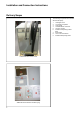
Installation and Connection Instructions Transport and Setup Transport Before every transport, make sure the lifting or transport equipment has the lifting power needed to transport the respective equipment weight. All of the tasks described here must be carried out based on the relevant safety standards. This applies to tasks associated with the equipment as well as the process or procedure of each task itself.
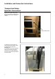
Installation and Connection Instructions Transport and Setup Hydraulic Connections After the unit is placed into position, make sure to check for visible damage. Properly dispose off the packaging material. Transport safety device The flexible connection tubes and hoses included in the delivery scope are attached to the rear of the AQUATOP TC.
Installation and Connection Instructions Heat Reclamation Connection Geothermal Heating System / Geothermal Tube Collector Connections Connection pipes and distributor Delivery/installation by ELCO/ installation company On-site Trenches and openings Installed in compact heat pumps Heat Pump Connection Heat source booster pump and safety devces, connection lines, insulation, heat carrier fill Probe depth Delivery/installation by ELCO/ installation company Geothermal Heating System Boreholes for geotherma
Installation and Connection Instructions Heat Reclamation Connection Water (with intermediate circuit) Connections • Tapping and return lines • Trenches and opening Delivery/installation by installation company or builder Intermediate Circuit • Poss. groundwater pump • Establishing intermediate circuit incl.
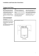
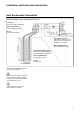
Installation and Connection Instructions Heater-Side Connection Key 1 Heating water outlet, inside thread 2 Heating water inlet, inside thread 3 Heat source outlet, inside thread 4 Heat source inlet, inside thread 5 Electrical feed 6 Sensor cable 7 Safety valve outlet 11
Installation and Connection Instructions Heater-Side Connection Two different basic concepts exist: a) Direct connection, without buffer storage, comply with min. circulating water volume requirement The coil area of the service water storage must be adjusted to the heat pump capacity. b) Indirect connection, with buffer for hydraulic decoupling The coil area of the service water storage must be adjusted to the heat pump capacity.
Installation and Connection Instructions Condensate and Safety Line The condensate line and the safety line of the heating side must be installed freely visible and at an incline towards the building drainage system. L The safety line of the heat reclamation side (heat gain with brine) must be installed freely visible and at an incline, leading into a suitable collection container.
Electrical Connection General E Compliance with the corresponding SEV, EN, IEC, as well as the corresponding VDE standards is required for the electrical connection of the heat pump. The connection specifications of the local utility or electric company must be complied with as well. E The power supply to the equipment must be interrupted before each electrical connection or service or maintenance work. The upper cover on the equipment must be removed for the electrical connection.
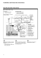
Electrical Connection Wiring Diagram and Terminal Assignment On-site setup Electric company block Flow monitor Contact closed – HP released Heat pump HP supply Load Terminals in HP (optional) Heat pump Power consumption Ext. fuse Switching valve Malfunction Heizungsregler Heat pump Exterior sensor L The sensors, pumps, mixing valves, etc. to be connected may vary depending on the system configuration and are listed in the corresponding standard documentation.
Assembly Control Panel The front cover, the controller case, and the control panel are to be assembled in the following order: Connection Plug to Control Panel 1 Insert the connection plug to the control panel through the opening in the front upper cover plate. Connection Plug to Control Panel 2 Insert Controller Receptacle into Upper Front Cover Plate The controller receptacle is inserted into the 4 lengthwise grooves of the upper front cover panel.
Assembly Control Panel Insert Control Panel into Controller Case Attach Front Cover Insert the front cover panel into the controller case from bottom to top while holding at a slant. Snap Front Cover into Place Snap front cover into the provided lengthwise grooves.
Charging Geothermal Heating Systems Problems and Issues Incorrect Brine Concentration Flushing Problems Problems with charging a geothermal heating system (GHS) with antifreeze may occur occasionally and result in a reduced capacity of the system or even total system failure. Most problems are as follows: Dirt in the Circuit Drilling companies generally strive to fill only clean water into geothermal heating systems. However, dirt may reach the probe due to inattention.
Charging Geothermal Heating Systems Charging with Antifreeze Correctly Charging a Geothermal Heating System Circuit Charging with Antifreeze After flushing, the entire geothermal heating system circuit is to be filled with clean tap water. Follow the steps below to prepare the required concentration of antifreeze with a 100% concentrate. For example: The required antifreeze concentration is 25% (ideal range is 25-30%) with a 140-m Duplex® ø 32 mm BHE. (Content per meter = 4 pipes x 10 dm, length x 0.
Charging Geothermal Heating Systems Charging with Antifreeze Correctly Charging a Geothermal Heating System Circuit Heating and Brine Charging Valves L The brine circuit is to be charged with a charging pressure of 1 bar (diaphragm-type expansion vessel initial pressure) + 0.3 bar as brine header = total of 1.3 bar. L The temperature difference during this operation should not exceed 4 K between sole inlet and outlet. Flushing and charging (heating side).
Initial Startup Heat Pump Controller LOGON B RVS51 1 2 4 3 5 6 8 9 7 RESET Control Based on Atmospheric Conditions, Featuring the Following: • lluminated display, status and function indicators in plain text. • Standard program default setting, setpoints, date, time. • Automatic switching between summer/winter time. • Preset standard timed programs for heating and hot water heating. • Complete control and monitoring of the HP incl. 2 heating circuits and potable water heating, buffer in one unit.
Initial Startup Quickstart LOGON B RVS51.843, Control Elements Control Units Select potable water operation Control Panel AVS37.294/309 Select heating operation Control unit installation variations: Snapped into HP front panel (interior HP setup) or inside the building, with the help of the wall mounting plate, attached to wall (exterior HP setup). Display information Apply setting Reset / defrost key Exit setting Service plug (BSB) Room Controllers QAA75... QAA75.611 /301: Room controller, wired.
Initial Startup Quickstart LOGON B RVS51.
Initial Startup Basic Display Key Action How To Display/Function Factory setting: Automatic Mode ON The automatic operating mode adjusts the room temperature as set with the timer program. D C Continuous operation or Keeps the room temperature at the selected operating level.
Initial Startup Basic Display Key Action How To Display/Function Cooling operation Switch ON or Off - Cooling operation ON/OFF (Bar under cooling cycle symbol visible/ hidden) Press key 1x Passive cooling via HP switched ON/ OFF. The "cooling" operating mode adjusts the room temperature as set with the timer program. Cooling mode characteristics: Manual cooling mode Cooling operation acc. to timer program Temp. setpoint acc.
Initial Startup Basic Display Key RESET Action How To Reset and defrost function - Press key 1x and less than 3 seconds Display/Function Triggers reset Any pending heat pump error messages, counters, and other resettable parameters are reset all at one when pressing this key. The preset switching-on delay in case of malfunctions is thereby bridged.
Initial Startup Parameterization Initial startup (sometimes referred to as "commissioning") involves the following tasks: • The correct assembly, setup, and electrical installation are prerequisites. • Make all system-specific adjustments. The "configuration" control side is particularly important. Select the corresponding control level as follows: • On the room controller, use OK to switch to programming.
Initial Startup Factory settings Max Min Unit Function Control level Control line Parameterization Timer program 520 . . . 536 (same as timer program heating circuit 1) heating circuit 2 Timer program 3 / HCP Timer program 4 / PWH Vacation heating circuit 1 540 E Preset value - 541 E 1. phase ON hh:mm 542 E 1. phase OFF Mon - Sun, Mo - Fri, Sat - Sun, Mon, Tue, Wed, Thu, Fri, Sat, Sun 00:00 24:00 Mon - Sun 06:00 22:00 543 E 2. phase ON --.-- 544 E 2. phase OFF --.-- 545 E 3.
Initial Startup Cooling circuit 1 Heating circuit 2 Heating circuit P 901 E Operating mode - OFF 902 E Comfort setpoint °C Value from control line 710 907 E Release 908 I 909 I 912 923 - 24h/day, timer program heating circuit, timer program 3/HCP, timer program 4/PWH Factory settings Max Min Unit Function Control line Control level Parameterization 24h/day Flow setpoint at ExT 25°C °C 8 35 20 Flow setpoint at ExT 35 °C °C 8 35 16 E Cooling limit at ExT °C 8 35 24
Initial Startup Solar Buffer storage Potable water storage Configuration 30 3810 3811 3812 3830 3831 3840 3850 3860 4709 F F F F F F F F I Temp. diff. ON exchanger 1 Temp. diff. OFF exchanger 1 Load temp. min. exchanger 1 Collector start function Min. run time collect. pump Collector frost protection Collector overheat protection Evapor.
Initial Startup Failure Maintenance Service 5952 I Min.
Initial Startup Factory settings Max I Relay test 7730 I Exterior temperature B9 °C 7732 I Flow temperature B1 °C 0 140 - 7750 I B3 potable water temperature °C 0 140 - 7770 I Flow temperature HP B21 °C 0 140 - 7771 I Return temperature HP B71 °C 0 140 - 7772 I Hot gas temperature B81 °C 0 140 - 7775 I Source input temp.
Initial Startup Min Max Factory settings I Compressor 1 K1 - OFF ON - 8401 I Compressor 2 K2 - OFF ON - 8402 I Electr. immers.
Initial Startup 34 -50 8700 E Exterior temperature 50 8701 E Exterior temperature min °C -50 50 8702 E Exterior temperature max °C -50 50 8703 I Exterior temperature damped °C -50 50 8704 I Exterior temperature mixed °C -50 50 8730 I Heating circuit pump Q2 °C OFF ON 8731 I Heating circuit mixing valve open Y1 - OFF ON 8731 I Heating circuit mixing valve open Y2 - OFF ON 8740 E Room temperature 1 °C 0 50 8741 E Room setpoint 1 °C 4 35 8743 E Flow temp
Troubleshooting Troubleshooting AQUATOP LOGON WP Malfunction Cause Remedy, Action 106: Source temperature too low B-W HP Brine output temperatures too low (parameter 2816, -5°C) A1 Low volume flow A2 Geothermal heating system badly charged A3 Geothermal heating system comp.
Troubleshooting Troubleshooting AQUATOP LOGON WP Malfunction Cause 223: HP when starting HC A High pressure malfunction when starting heating circuit. Water in system too cold. Remedy, Action A Below 10 °C: Increase temperature in system with electr. immersion heater. 224: HP when starting potable water heating High pressure malfunction when starting PWH. Service water operation.
Troubleshooting Troubleshooting AQUATOP LOGON WP Malfunction Cause Remedy, Action 228: Flow controller water source A W-W heat pump No flow A1 Checker whether corresponding sliders are opened A2 Check function flow switch (while keeping groundwater pump running, check switching point of flow switch by slowly closing/opening slider) A3 Check function of groundwater pump 229: Pressure monitor A GHS/geothermal probe/tube collector system B-W heat pump Brine pressure too low The module switches the resp
System Characteristic Curves NTC 1 k Characteristic Curves NTC 10 k Characteristic Curve NTC 1K for Exterior Temperature Sensor B9 T [°C] -30.0 -29.0 -28.0 R[Ohm] 13'034 12'324 11'657 T [°C] 0.0 1.0 2.0 R[Ohm] 2'857 2'730 2'610 T [°C] 30.0 31.0 32.0 R[Ohm] 827 796 767 -27.0 11'031 3.0 2'496 33.0 740 -26.0 -25.0 10'442 9'889 4.0 5.0 2'387 2'284 34.0 35.0 713 687 -24.0 9'369 6.0 2'186 36.0 663 -23.0 -22.0 8'880 8'420 7.0 8.0 2'093 2'004 37.0 38.0 640 617 -21.0 -20.
Equipment Dimensions AQUATOP T05C+T06C, T08C-T14C, T07C-HT, T11C-HT, T19C Dimensional Drawing Front view (control side) Right view Left view Plane view with min.
Technical Data AQUATOP T05C-T10C Heat Pump Type AQUATOP T05C Model Type T06C T08C T10C Compact Heat Pumps Standard Data Heat Pumps Brine W35 W50 W35 W50 W35 W50 W35 W50 Heating capacity (Qh) B0 kW 5.4 5.0 6.5 6.1 8.2 7.7 9.6 9.0 Cooling capacity (Qo) B0 kW 4.2 3.3 5.0 4.0 6.3 5.0 7.4 5.9 El. power consumption 1) (Pe) B0 kW 1.2 1.8 1.5 2.1 1.9 2.7 2.2 3.1 Performance rating 1) (COP) B0 (-) 4.5 2.8 4.3 2.7 4.4 2.8 4.5 2.
Technical Data AQUATOP T05C-T10C Heat Pump Type AQUATOP T05C T06C T08C T10C Electrical Data Operating voltage, feed Rated input with B0 / W35 3 x 400 V PNT Ext. fuse kW 1.2 1.5 1,9 2.2 AT 13 13 13 16 Rated current immersion heater l max. A 10 10 10 10 Rated current heat pump I max. A 4.2 5.1 5.6 7.0 Current with blocked rotor (LRA) LRA A 24 32 40 46 Starting current with soft starter VSA A 12.5 17.5 17.5 17.5 Power consumption el. immersion heater max.
Technical Data AQUATOP T12C-T19C Heat Pump Type AQUATOP T12C Model Type T14C T19C Compact Heat Pumps W35 W50 Standard Data Heat Pumps Brine W35 W50 W35 W50 Heating capacity (Qh) B0 kW 12 11.3 14.4 13.5 18.5 17.3 Cooling capacity (Qo) B0 kW 9.2 7.6 11.1 9 14.5 11.9 El. power consumption 1) (Pe) B0 kW 2.8 3.8 3.3 4.5 4.0 5.5 Performance rating 1) (COP) B0 (-) 4.3 3.0 4.3 3.0 4.6 3.2 Heating capacity (Qh) W10 kW 15.9 14.7 19.1 17.5 24.5 22.
Technical Data AQUATOP T12C-T19C Heat Pump Type AQUATOP T12C T14C T19C Electrical Data Operating voltage, feed Rated input with B0 / W35 3 x 400 V PNT Ext. fuse kW 2.8 3.3 4.0 AT 16 20 20 Rated current immersion heater l max. A 10,0 10,0 10,0 Rated current heat pump I max. A 10,0 12,4 14,0 Current with blocked rotor (LRA) LRA A 50 66 74 Starting current with soft starter VSA A 25 27.5 33.8 Power consumption el. immersion heater max.
Technical Data AQUATOP T07C-HT, T11C-HT Heat Pump Type AQUATOP T07C-HT Model Type T11C-HT Compact Heat Pumps W35 W50 Standard Data Heat Pumps Brine W35 W50 Heating capacity (Qh) B0 kW 7.3 7.2 10.9 10.5 Cooling capacity (Qo) B0 kW 5.7 5.0 8.6 7.4 El. power consumption 1) (Pe) B0 kW 1.6 2.2 2.3 3.1 Performance rating 1) (COP) B0 (-) 4.6 3.2 4.7 3.4 Heating capacity (Qh) W10 kW 9.6 9.2 14.1 13.6 Cooling capacity (Qo) W10 kW 8.0 6.9 11.7 10.4 El.
Technical Data AQUATOP T07C-HT, T11C-HT Heat Pump Type AQUATOP T07C-HT T11C-HT Electrical Data Operating voltage, feed Rated input with B0 / W35 3/N/PE400V/50Hz PNT Ext. fuse kW 1.6 2.3 AT 16 20 Rated current immersion heater l max. A 10.0 10.0 Rated current heat pump l max. A 10.0 13.5 Current with blocked rotor (LRA) LRA A 50 74 Starting current with soft starter VSA A 25 40 Power consumption el. immersion heater max. kW Power consumption circulating pumps max.
Initial Startup Log Initial Startup Log Order No. Report. E For Report No. Unit address Flow Name Street Address Compressor Evaporator ZIP/City Installation company 1 Condensation temperature °C 2 Condensation pressure HP bar 3 Hot gas temperature °C 4 Heating flow temperature °C 5 Heating return temperature °C Schema Nr. 6 Subzero cooling temperature °C Construction heating 7 Heat source output temperature °C ZIP/City Unit type Fabrikat Year of manuf. Erzeugnis Nr.
Notes 47
Service: ELCO GmbH D - 64546 Mörfelden-Walldorf ELCO Austria GmbH A - 2544 Leobersdorf ELCOTHERM AG CH - 7324 Vilters ELCO-Rendamax B.V. NL - 1410 AB Naarden ELCO Belgium n.v./s.a.