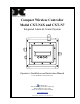
Compact Wireless Controller Model CXT-N4X and CXT-N7 Integrated Alarm & Control System Operator’s Installation and Instruction Manual Covers all Model CXT Control Units DETCON, Inc. 4055 Technology Forest Bvd. Suite 100, The Woodlands, Texas 77381 Ph.281.367.4100 / Fax 281.298.2868 www.detcon.com April 10, 2012 • Document #3756 • Revision 0.
Model X40 This page left intentionally blank Shipping Address: 4055 Technology Forest Bvd. Suite 100, The Woodlands Texas 77381 Mailing Address: P.O. Box 8067, The Woodlands Texas 77387-8067 Phone: 888.367.4286, 281.367.4100 • Fax: 281.292.2860 • www.detcon.com • sales@detcon.com Model X40 Instruction Manual Rev. 0.
Model X40 Table of Contents 1. Introduction............................................................................................................................................1 1.1 1.2 2. Installation..............................................................................................................................................3 2.1 2.2 2.3 3. 4. Description ............................................................................................................................
Model X40 Figure 4 CXT-N4X Controller Mounting and Dimensional View .................................................................3 Figure 5 CXT-32-N7 Controller ......................................................................................................................4 Figure 6 Model 100 Terminal Board ...............................................................................................................5 Figure 7 Model 100 Terminal Board Rotary Switches..............................
Model X40 This page left intentionally blank Shipping Address: 4055 Technology Forest Bvd. Suite 100, The Woodlands Texas 77381 Mailing Address: P.O. Box 8067, The Woodlands Texas 77387-8067 Phone: 888.367.4286, 281.367.4100 • Fax: 281.292.2860 • www.detcon.com • sales@detcon.com Model X40 Instruction Manual Rev. 0.
Model X40 1. Introduction 1.1 Description The Detcon CXT controller is a multi-channel gas detection controller designed to serve as a host monitor and for a wireless network of up to 32 CXT Sensors and a variety of wireless alarm stations. The CXT controller, sensors and alarm stations utilize radios based upon the IEEE 802.15.4 standard that operate at 2.4 GHz using DSSS encoding for robustness. These units are designed for low power operation using Detcon rechargeable battery packs.
Model X40 1.2 System Operation The heart of the CXT controller is the non-intrusive magnetic interface with backlit LCD display. The controller communicates with sensors and alarm stations using RS-485 Modbus™ RTU protocol distributed over a wireless network. The CXT controller includes a wireless transceiver that communicates directly with Detcon’s CXT sensors and Detcon Wireless Alarm Stations using the RXT-320 Transceivers.
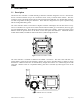
Model X40 2. Installation 2.1 NEMA 4 units The CXT-N4X controller is housed in a NEMA 4X water/corrosion proof stainless steel enclosure for indoor/outdoor use. Securely mount the Model CXT-N4X enclosure per the mounting dimensions provided in Figure 4 Power is provided by a battery pack. that can be charged by an external battery charger. No other outside connections or wiring is utilized, as the unit is self contained. 14 Mounting Bracket 12.00" 10" 4.2" 3.72" Ø0.27" 12.75" 13.75" 11.
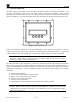
Model X40 2.2 NEMA 7 Units The Model CXT-32-N7 controller is housed in an explosion proof NEMA 7 enclosure for indoor/outdoor use and comes neatly packaged and mounted on a mounting plate designed for 2~3” pole mounting. Securely mount the Model CXT-32-N7 per the mounting dimensions provided in Figure 5. No outside connections are expected for operation. 24.75" 3.5" 16.75" Typ. CXT Controller 8.25" 11" J-Box w/ Transceiver and interconnect terminal board Intrinsically Safe Reset Switch.
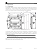
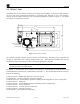
Model X40 S S E L E R I W V / W ︶ V 4 2 D A N G B ︵ ︶ 2 A D N N I A M G R W P 7 J V 4 2 2 W S D A N G 1 J B N IR RA EL WO OS P 2 J 8 J T US OS E SL UE BR DI OW M ︵ U N B / G / W W SM SA E LR EG RO IR WP 1 K N B N B / I / W W A 6 J 4 J 1 W S V D 4 N 2 G A B R O S N E S N I S U B D O M 5 J L A 1 C D P S S S 2 P S 1 P J MM RA ER TG O R P R D W N P G Y A L P S I D 9 L Figure 6 Model 100 Terminal Board The Model 100 Terminal Board also contains two rotary switches which are u
Model X40 3. Secure Digital Card The CXT controller has a feature that allows data logging when a secure digital (SD) memory card is installed. The SD card must be installed in the SD slot (J9) on the back of the controller’s PCA before the controller is powered up. The controller will notify the user if a successful installation of the card was achieved upon power up. The controller will automatically format the card and create the necessary files for data logging. See section 4.3.
Model X40 System Operation and Configuration 4. The setup of the controller is critical for proper operation. Modbus™ addresses must be correct on all the devices connected to the controller before the controller will acknowledge them. The number of sensors must be entered into the controller to allow it to communicate with them. Four basic areas need to be configured: ¾ The number of sensors must be determined before setup begins.
Model X40 silence alarms once the end-user has assessed the alarm condition. The RESET/ACKNOWLEDGE function of the switch is only applicable from the Main Display and not while in Main Menu mode. m e t s y S l o r t n o C & m r a l A d e t a r g e t n I Figure 9 Front Panel User Interface NOTE: The controller automatically times out of Main Menu mode and returns to the Main Display after 15 seconds of inactivity. NOTE: The RESET/ACKNOWLEDGE function is applicable from the Main Display only. 4.
Model X40 3) 4) 5) 6) 7) 8) 9) 10) 11) 12) 13) 14) 15) 16) 17) 18) SET # OF RXT-320S SET RF SILENCE AND RF SLEEP SET COMM BAUD RATES SET MODBUS TIMEOUTS SETUP CHANNEL DATA SET CHANNEL ALARMS SET LOW BATTERY ALARMS SET RELAY FUNCTION FLASHING BLUE LED CODES SET MODBUS ADDRESS INHIBIT & ALARM TEST MODE RF LINK QUALITY AND BATTERY STATUS SYSTEM DIAGNOSTICS DISPLAY SETTINGS TIME AND DATE VIEW TWA & PEAK The PROG switch is used to enter the menu mode of the unit by swiping a programming magnet over the corres
Model X40 MAIN DISPLAY MAIN MENU NORMAL OPERATION SET LOW BATTERY ALARMS TTE(DD:HH:MM): ##:##:## SOC(%): ###% Multiple Relays (Fault, Alm1, Alm2, Alm3) MAIN MENU AUTO CONFIGURE SYSTEM MAIN MENU SET # OF CHANNELS/AO4S/ RL4S/ALARM STATIONS MAIN MENU CHANNELS: ## AO4S: # RXT-320S:## RL4/ALM BANK 1: # RL4/ALM BANK 2: # MAIN MENU SET RELAY FUNCTION CHANNELS: ## AO4S: # BANK 1: # BANK 2: # MAIN MENU FLASHING BLUE LED CODES RXT 320S: ## SET # OF RXT-320S MAIN MENU SET RF SILENCE AND RF SLEEP RF SILE
Model X40 address 7Fh is reached or until it is terminated by swiping the ENTER marker which will save the serial sensors found up to that point and proceed to search for available RL4 modules starting with Modbus™ address 80h. The search will continue until Modbus™ address 87h is reached or until it is terminated by swiping the ENTER marker which will save the RL4 modules found up to that point and proceed to search for available AO4 modules starting with Modbus™ address A1h.
Model X40 To abort the search, swipe the PROG marker while in search mode. The unit will abort the search and will not save any CXT sensors or RXT-320’s found up to that point. 4.3.4 Set RF Silence and RF Sleep The SET RF SILENCE AND RF SLEEP menu allows the user to initiate radio silence over the whole network. Radio silence terminates communication between all the RXT-320 transceivers in the network. This menu also allows the user to initiate RF sleep for a set amount of time.
Model X40 These values can be changed by swiping the magnet over the markers of the up or down arrows to move the arrow prompt “→” to the desired function. A swipe over the ENTER marker will select the function indicated by the arrow prompt “→” and the value can be changed by swiping over the markers of the up or down arrows. Another swipe over the ENTER marker will save the selected value.
Model X40 underscore and can be changed by swiping the magnet over the markers of the up or down arrows. A swipe over the ENTER marker will select the displayed value and the next character to be changed will be indicated by the underscore. Follow these same steps to input all nine characters. The last swipe over the ENTER marker will return to the flashing cursor.
Model X40 4.3.9 Set Low Battery Alarms The SET LOW BATTERY ALARMS menu allows the user to set low battery alarm thresholds for Detcon Smart Battery Packs used with CXT sensors and RXT-320 transceivers. Upon entering this menu, the LCD will display: LOW BATTERY ALARM: TTE(DD:HH:MM): | SOC(%): ##:##:## | ##% | ALARM STATIONS ONLY TTE represents the time to empty and will be displayed in days, hours and minutes. SOC represents the state of charge and will be displayed as a percentage value.
Model X40 There are four relay outputs per bank. Three relay outputs are used for ALM1, ALM2 and ALM3 and the fourth relay output is used for the FAULT condition. All four relay outputs in both banks must be set-up to account for the following three settings: Latching or Non-Latching, Energized or De-Energized and Silenceable or Non-Silenceable. The values selected can be either Y (Yes) or N (No). NOTE: It is generally recommended to set the FAULT relay as energized so that it will trip upon loss of power.
Model X40 These values can be changed by swiping the magnet over the markers of the up or down arrows to move the arrow prompt “→” to the desired function. A swipe over the ENTER marker will select the function indicated by the arrow prompt “→” and the value can be changed by swiping over the markers of the up or down arrows. Another swipe over the ENTER marker will save the selected value. The INHIBIT MODE has a timer range from 0-60 minutes.
Model X40 user will be prompted again to “press any key” and the alarm 3 relay will be turned on. The user will be prompted again to “press any key” and the fault relay will be turned on. The user will be prompted again to “press any key” and all the relays will be reset. The user will then be prompted to connect COMM1 (master) to COMM2 (slave) for a Modbus™ loop back test and “press any key” to continue. This will initiate test 1 of 4 which performs a Modbus™ communication test at 4800 baud rate.
Model X40 to the desired field. A swipe over the ENTER marker will select the field indicated by the arrow prompt and the value can be changed by swiping over the markers of the up or down arrows. Another swipe over the ENTER marker will save the selected value. Once the desired values have been set, move the arrow prompt to “Change Date” and swipe the ENTER marker to update the date with the changes entered.
Model X40 5. Troubleshooting Guide Problem Unit will not Power Up Relays are not firing Alarms on constantly Alarm Firing causes unit to ‘LockUp’ Potential Fix → Check for correct AC or DC voltage selection. → Check for correct VAC and VDC powering configuration. → Check that the alarm relays are configured properly → Insure that no channels are set to ascending or descending incorrectly. → Check that Alarm Annunciators current draw does not exceed the on-board Power Supply limitations.
Model X40 7. Specifications System Specifications Capacity: Warranty: 32 Sensors One year Electrical Specifications N4X, N7 Input Voltage: Power Consumption: RFI/EMI Protection: Electrical Classification: Battery Operation. CXT Controller and transceiver Complies with EN61326 NEMA 4X or NEMA 7 Mechanical Specifications Display: Dimensions: 1 ¼” x 6” Backlit LCD CXT-32-N1P – 10.5” W x 8” H x 12” D CXT-08-N4X – 11.85” W x 13.75” H x 6.5” D CXT-32-N4X – 16” W x 17.85” H x 8.5” D CXT-32-N7 – 11.
Model X40 7.2 Revision Log Revision Date 0.0 04/10/12 Changes made Initial Release. Shipping Address: 4055 Technology Forest Bvd. Suite 100, The Woodlands Texas 77381 Mailing Address: P.O. Box 8067, The Woodlands Texas 77387-8067 Phone: 888.367.4286, 281.367.4100 • Fax: 281.292.2860 • www.detcon.com • sales@detcon.com Model X40 Instruction Manual Rev. 0.