
Instruction manual

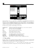


RXT Wireless Configuration Tool
RXT WCT Instruction Manual Rev 0.0 Page 22 of 33
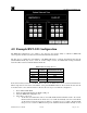
5.0 Example RXT-300 Configuration
The RXT-300 configuration tool gives the user the ability to add/remove RXT-300s to/from specific wireless
networks based on their Channel and Network ID plus allows the user the ability to configure RXT-300
wireless systems.
The first step is to identify the serial numbers of the RXT-300s that will be part of the wireless system and to
define the parameters for the system much like the information needed when setting up a control system for a
gas detection system. In this sample exercise, five RXT-300s residing in different networks will be added to
Channel 10/Network ID 10 and configured per their respective function:
Table 2 RXT-300 Sample Exercise
RXT-300
Serial
Number
New Network
(Channel/Network ID)
Function
RXT 1 00.83.49 10/10 700 Sensor 1
RXT 2 00.85.3A 10/10 100 Sensor 2
RXT 3 00.85.43 10/10 Alarm Station 1
RXT 4 00.90.6E 10/10 4-20 Analog Input
RXT 5 00.90.78 10/10 HMI Panel
If the current wireless network of an RXT-300 is not known, the WCT can be used to obtain such information.
What is important is to know the serial number of the particular RXT-300 and to know which wireless network
it should reside in. Once this information is known, the user can proceed with the configuration.
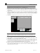
1. Power ON the RXT WCT.
2. Insert the USB SNAP Stick in the WCT’s USB port.
3. Select the RXT-300 configuration tool.
4. Select Create Configuration File
Network/Zone Tab
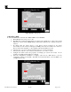
5. This screen will have three tabs to choose from, each tab with specific configurations to be entered by
the user accordingly. The first tab is the Network/Zone(s) tab and will already be active by default.
This tab is used to enter the network information for the wireless system and the alarm zones needed.
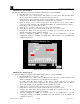
a. Select the System Name field and enter a system name no more than 32 characters long. In
this example, the system name will be “Wireless Network Example”.
b. Select the Network ID field and enter the network ID. In this example, the network ID will be
“10”.
c. Select the RF Channel field and enter the channel for the network. In this example, the
channel will be “10”.
d. The Network Sleep Time(s) default value is 10, but can be changed if needed. In this example,
the network sleep time will remain at “10”.
e. Select the Save button for the Network section which will save the values entered for System
Name, Network ID, RF Channel and Network Sleep Time.
f. Select the Add Zone(s) button which turns on Add Mode and displays the first zone with a
default name of “Zone 1”. This name can be changed by the user if desired and must be no
more than 32 characters long. In our example, two zones will be created.
NOTE: Up to 16 independent zones can be created. The network configuration must contain
at least one zone.