
Instruction manual


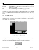


RXT Wireless Configuration Tool
RXT WCT Instruction Manual Rev 0.0 Page 9 of 33
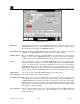
Device Name Alphanumeric name for the corresponding sensor in the system which can be set to a
meaningful name by the user. A maximum of 32 characters is allowed of which only the
first 15 characters will appear on an HMI Panel display.
Device Type The user can select from a pre-defined list of Detcon devices which will automatically
populate some of the parameters for the user. The available device types are 100 Series,
600 Series, 600D Series, 700 Series and RXT-300.
RXT The user selects from a list of RXT-300s using the RXT name that identifies the RXT-300
this device is attached to. The RXT-300 must be added first.
Modbus Address Sets the system wide Modbus™ address of this device. The address will auto-increment
to the next Modbus™ address as each device is added and starts at address 1.
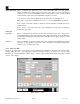
Device Modbus
Address Sets the address of the device local to this RXT-300. This will be the same as the
Modbus™ address set above unless it is a 100 series sensor without the LED display
which will have a fixed address of 1. The system wide Modbus™ address is translated on
this RXT-300 to the Device address. For example, if the Modbus™ address is set to 4 and
the Device address is set to a 1, the RXT-300 will poll address 1 on its local Modbus™
interface but will present this to the network as Modbus™ address 4. So the HMI Panel
will actually request sensor data from Modbus™ address 4 in this instance.
Range Defaults to 100 but defines the range of readings that will be read from a device. For 4-
20mA devices, a reading of 400 to 2000 represents 4mA to 20mA. If a range of 100 is
entered internally, the RXT-300 will translate Alarm thresholds entered later into the
appropriate 4-20mA thresholds internally. So if an Alarm threshold is set to a value of 10,
this is 10% of the 4-20mA reading which equates to a reading of 560 internally.
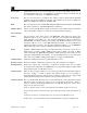
Starting Register Defines the starting address used to poll the Modbus™ device.
Registers to Read Defines the number of Modbus™ registers to read. This is limited to 22 registers.
Reading Register Defines the register that contains the concentration (reading) value used for Alarm
processing and for displaying on an HMI Panel. It is the physical register number with 0
being the first register on a Modbus™ device.
Alarm Setpoints There are three setpoints: Alarms 1, 2 and 3 that represent the three Alarm thresholds for
the sensor reading. A value is entered and defined whether it is an ascending or
descending threshold. Every time the device is read the reading value is compared with
this threshold and will generate an Alarm event if the threshold is crossed.
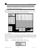
Alarm Out Events This is a submenu that allows the user to select which device events will generate alarms
and which relays are triggered. There are six events that are monitored: Alarm 1,
Alarm 2, Alarm 3, Fault, Communication Error and Modbus Exception. These can be
mapped to any of the four relays.
Alarm 1, Alarm 2, Alarm 3 events occur when the user defined setpoints are crossed.
Fault is monitored if it is a Detcon device type and the device has a fault status that can be
read.
Communication Errors occur when there is no response from a Modbus™ read.
Modbus Exception occurs when the device returns Modbus™ exceptions during a read.