
Manual
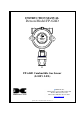

Model FP-624D
FP-624D Instruction Manual iv
List of Figures
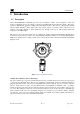
Figure 1 Sensor Assembly Front View............................................................................................................ 1
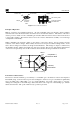
Figure 2 Sensor Cell Construction .................................................................................................................. 2
Figure 3 Wheatstone Bridge ........................................................................................................................... 2
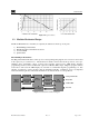
Figure 4 Response Curves .............................................................................................................................. 3
Figure 5 Circuit Functional Block Diagram .................................................................................................... 3
Figure 6 Transmitter Module.......................................................................................................................... 4
Figure 7 Field Replaceable Combustible Gas Sensor....................................................................................... 4
Figure 8 Base Connector Board...................................................................................................................... 5
Figure 9 Typical Outline and Mounting Dimensions....................................................................................... 8
Figure 10 Typical Installation......................................................................................................................... 9
Figure 11 Sensor Connector PCB ..................................................................................................................10
Figure 12 Remote Sensor Wiring Diagram.....................................................................................................11
Figure 13 Magnetic Programming Tool .........................................................................................................13
Figure 14 Magnetic Programming Switches...................................................................................................13
Figure 15 FP-624D Software Flowchart.........................................................................................................15
Figure 16 Replaceable Combustible Gas Sensor ...........................................................................................34
Figure 17 Plug-in Sensor (Bottom View).......................................................................................................34
List of Tables
Table 1 Wire Gauge vs. Distance...................................................................................................................10
Table 2 Gas/Cal Factors.................................................................................................................................22
Table 3 Modbus Registers .............................................................................................................................30
Table 4 Notation Text String Description.......................................................................................................31
Shipping Address:
4055 Technology Forest Blvd, Suite 100,
The Woodlands Texas 77381
Mailing Address: P.O. Box 8067, The Woodlands Texas 77387-8067
Phone: 888.367.4286, 281.367.4100 • Fax: 281.292.2860 • www.detcon.com • sales@detcon.com