
Manual


Model FP-624D
FP-624D Instruction Manual Rev. 1.2 Page 30 of 42
4. RS-485 Modbus
TM
Protocol
Model FP-624D sensors feature Modbus™ compatible communications protocol output and are addressable
via the program mode. Communication is via a two wire, half duplex RS-485, 9600 baud, 8 data bits, 1 stop
bit, no parity, with the sensor set up as a slave device. A master controller up to 4000 feet away can poll up to
256 different FP-624D sensors. This number may not be realistic in harsh environments where noise and/or
wiring conditions would make it impractical to place so many devices on the same pair of wires. If a multi-
point system is being utilized, each sensor should be set for a different address. Typical address settings are:
01, 02, 03, 04, 05, 06, 07, 08, 09, 0A, 0B, 0C, 0D, 0E, 0F, 10, 11…etc.
Sensor Serial ID numbers are factory default to 01. These can be changed in the field via the Operator
Interface described in Section 3.5.8.
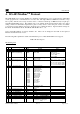
The following table explains the details of the Modbus™ protocol that the FP-624D sensor supports.
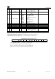
Table 3 Modbus Registers
Modbus Registers
FC REG Content Description R/W Content Definition
Value Meaning Range
03
40000
Device Type
R
8
700 Sensor
03
40001
Read Detectable Range
1,2
R/W
100
For 0
-
100
DM
–
0 to 10000
06 40001 Write Detectable Range 10000 For 0-10000
2
FP – Read only
TP – 20, 50, 100, 200
IR – 0 to 10000
PI – 0 to 10000
03 40002
Read Concentration
3,2
R 1000 Bound by range. If > range, this
value is in fault.
03
40003
Read AutoSpan Level
4,2
R/W
50
Span gas at 50
DM
–
1% to 95% of Range
06
40003
Write
AutoSpan Level
FP
–
5% to 95% of Range (40001)
TP – 2% to 50% of Range (40001)
IR
–
5% to 95% of Range (40001)
PI
–
1% to 95% of Range (40001)
03 40004 Read Sensor Life R 85 For 85% sensor life
03
40005
Read Fault Status Bits
5
R
0x0001
Global Fault
0x0002 Auto Span Fault
0x0004
Temperature Fault
0x0008 4-20mA Fault
0x0010 Input Voltage Fault
0x0020 Memory Fault
0x0040
Processor Fault
0x0080 Clearing Fault
0x0100 Stability Fault
0x0200 Range Fault
0x0400 Sensor Fault
0x0800
Zero Fault
0x1 000 Sensor Fault 2
0x2000 <reserved>
0x4000
In Calibration
0x8000 Communication Error
03 40006 Read Model # R 1, 2, 3, 4, 5
DM, FP, IR, TP, PID
respectively
03 40007 Read Days Since Cal R 29 29days
03 40008
4-20 Current Output
mA x100
R 400 4.00mA
03 40009
Read Input Voltage
V x100
R 2400 24.00V
03 40010 Read Temperature R 28 28 °C
03/
06
40011 Special #1 R/W
Function Dependant on Value
of 40006
(See Special Register
FC REG Content Description R/W Content Definition
Value
Meaning
Range
03/
40012
Special #2
R/W
Function Dependant on Value
06
of 40006 (See Special Register
Table)