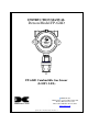
INSTRUCTION MANUAL Detcon Model FP-624D PGM MODEL 1 HOUSTON, TEXAS FP-624D MicroSafeTM LEL Gas Sensor FLT ALM ALM 1 2 CAL PGM 2 FP-624D Combustible Gas Sensor (0-100% LEL) DETCON, Inc. 4055 Technology Forest Blvd, Suite 100, The Woodlands, Texas 77381 Ph.281.367.4100 / Fax 281.298.2868 www.detcon.com April 23, 2012 • Document #3598 • Revision 1.
Model FP-624D This page left intentionally blank FP-624D Instruction Manual ii
Model FP-624D Table of Contents 1. 2. 3. 4. 5. 6. 7. 8. 9. Introduction............................................................................................................................................ 1 1.1 Description..................................................................................................................................... 1 1.2 Modular Mechanical Design........................................................................................................... 3 1.
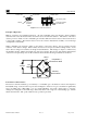
Model FP-624D List of Figures Figure 1 Sensor Assembly Front View............................................................................................................ 1 Figure 2 Sensor Cell Construction .................................................................................................................. 2 Figure 3 Wheatstone Bridge ........................................................................................................................... 2 Figure 4 Response Curves ......
Model FP-624D 1. Introduction 1.1 Description Detcon Model FP-624D combustible gas sensors are non-intrusive “Smart” sensors designed to detect and monitor combustible gases in air. Range of detection is 0-100% LEL (Lower Explosive Limit). The sensor features an LED display of current reading, fault, and calibration status. The sensor is equipped with standard analog 4-20mA, ModbusTM RTU output, and 3 relay contact outputs.
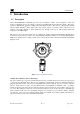
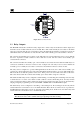
Model FP-624D Alumina Bead Platinum Wire Catalytic Beads Main Housing Insert Catalyst Printed Circuit Board Gold Plated Pins Construction of Detector Bead Figure 2 Sensor Cell Construction Principle of Operation Method of detection is by diffusion/adsorption. Air and combustible gases pass through a sintered stainless steel filter and contact the heated surface of both the active and reference detectors.
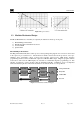
Model FP-624D Figure 4 Response Curves 1.2 Modular Mechanical Design The Model FP-624D Sensor Assembly is completely modular and is made up of four parts: 1) 2) 3) 4) FP-624D Plug-in Transmitter Field Replaceable Combustible Gas Sensor Connector PCB Splash Guard FP-624D Plug-in Transmitter The Plug-in Transmitter Module is a microprocessor-based package that plugs into the connector board located in the explosion proof junction box.
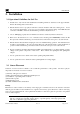
Model FP-624D PGM MODEL 1 HOUSTON, TEXAS FP-624D MicroSafeTM LEL Gas Sensor FLT ALM ALM 1 2 CAL PGM 2 Figure 6 Transmitter Module The transmitter module includes four LED status indicators (see Figure 3). These indicators are labeled FLT, ALM1, ALM2 and CAL. The ALM1 and ALM2 LEDs are illuminated when the sensor is above the corresponding alarm threshold. The FLT LED is illuminated when the sensor is in fault.
Model FP-624D Relays Customer Wiring Wiring to Figure 8 Base Connector Board 1.3 Relay Outputs The FP-624D includes three 5A Form C relay outputs. Two of these relays are dedicated to alarm outputs, and the third is used to indicate when the sensor is in fault. The common and normally closed contacts on the alarm relays are connected when the gas concentration is below the alarm threshold.
Model FP-624D 2. Installation 2.1 Operational Guidelines for Safe Use 1. Install sensor only in areas with classifications matching with those described on the approval label. Follow all warnings listed on the label. 2. Ensure that the sensor is properly mounted in a vertical orientation with sensor facing down. Avoid use of excessive Teflon Tape, or any type of non-conductive pipe thread coating on the NPT threaded connection. All NPT connections should remain grounded to the junction box. 3.
Model FP-624D Leak Sources The most probable leak sources within an industrial process include flanges, valves, and tubing connections of the sealed type where seals may either fail or wear. Other leak sources are best determined by facility engineers with experience in similar processes. Ventilation Normal ventilation or prevailing wind conditions can dictate efficient location of gas sensors in a manner where the migration of gas clouds is quickly detected.
Model FP-624D typical poisons are: silicone oils and greases, siloxanes (HMDS), H 2S, anti-knock petrol additives, and phosphate esters. Activated carbon filters can be used to provide additional protection from poisoning in most cases. The presence of such inhibitors and poisons in an area does not preclude the use of this sensor technology, although it is likely that the sensor lifetime will be shorter as a result.
Model FP-624D Proper electrical installation of the gas sensor is critical for conformance to Electrical Codes and to avoid damage due to water leakage. Refer to Figure 10 and Figure 11 for proper electrical installation. NOTE: If a conduit run exits the secondary port, repeat the installation technique shown in Figure 10. In Figure 10, the drain allows H2O condensation inside the conduit run to safely drain away from the sensor assembly.
Model FP-624D and 24VDC source is shown in the Table below. The maximum wire size for termination in the Junction Box is 14 AWG. Table 1 Wire Gauge vs. Distance AWG 22 20 18 16 14 Wire Dia. 0.723mm 0.812mm 1.024mm 1.291mm 1.628mm Meters Feet 700 1120 1750 2800 4480 2080 3350 5250 8400 13,440 Over-Current Protection 3A 5A 7A 10A 20A NOTE 1: Wiring table is based on stranded tinned copper wire and is designed to serve as a reference only.
Model FP-624D b) Observing correct polarity, terminate the field wiring (DC+, DC-, MA, A, and B) to the sensor assembly wiring in accordance with the detail shown in Figure 11. c) Trim all exposed wire leads if they are not permanently landed in the terminal block. d) Plug the Transmitter Module into the connector PCB and replace the junction box cover. NOTE: A 6-32 or 8-32 threaded exterior ground point is provided on most junction boxes for an external ground.
Model FP-624D This adjustment is only required after initial installation and will not be necessary thereafter, except in the event of replacement of the plug-in sensor. Refer to section 3.5.5 to perform this adjustment. NOTE: Refer to section 3.5.5 to set the sensor bridge voltage. 2.
Model FP-624D 3. Operation 3.1 Programming Magnet Operating Instructions The Operator Interface of the FP-624D gas sensors is accomplished via two internal magnetic switches located above and below the LED display (Figure 14). The two switches, labeled “PGM1” and “PGM2”, allow for complete calibration and configuration, thereby eliminating the need for area de-classification or the use of hot permits.
Model FP-624D 3.2 Operator Interface The operating interface is menu-driven via the two magnetic program switches located under the target marks of the sensor housing. The two switches are referred to as “PGM1” and “PGM2”. The menu list consists of three major items that include sub-menus as indicated below. (Refer to the complete Software Flow Chart.
Model FP-624D Software Flowchart Normal Operation PGM1 (3) PGM2 (3) PGM1 (3) PGM2 (3) Calibration Mode (Auto Zero) Calibration Mode (Auto Span) View Sensor Status Auto Time-Out PGM1/2 (M) PGM1/2 (3) Set AutoSpan Level Set Gas Factor Auto Time-Out PGM1/2 (M) PGM1/2 (3) AutoTime-out PGM1/2 (M) PGM1/2 (3) Set Bridge Voltage Set Cal Factor Auto Time-Out PGM1/2 (M) PGM1/2 (3) Auto Time-Out PGM1/2 (M) PGM1/2 (3) Model Type Version X.
Model FP-624D 3.3 Normal Operation In normal operation, the display continuously shows the current sensor reading, which will normally appear as “0”. Once every minute, the LED display will flash the sensor’s units of measure and the gas type (i.e. % LEL). If the sensor is actively experiencing any diagnostic faults, a “Fault Detected” message will scroll across the display once every minute instead of the units of measure and the gas type.
Model FP-624D c) The transmitter will display the following sequence of text messages as it proceeds through the AutoZero sequence: Zero Cal . . . Setting Zero . . . Zero Saved (each will scroll twice) d) Remove the zero gas and calibration adapter, if applicable. 3.4.
Model FP-624D Fault Status register will be set until the calibration is complete. c) Apply the span calibration test gas at a flow rate of 200-500cc/min (200cc/min is the recommended flow rate). As the sensor signal begins to increase, the display will switch to reporting a flashing “XX” reading as the display shows the sensor’s “as found” response to the span gas presented.
Model FP-624D The Program Mode menu items appear in the order presented below: View Sensor Status Set AutoSpan Level Set Gas Factor Set Cal Factor Set Bridge Voltage Signal Output Check Restore Default Settings Set Serial ID Alarm 1 Settings Alarm 2 Settings Fault Settings Navigating Program Mode From Normal Operation, enter Program Mode by holding the magnet over PGM2 for 4 seconds (until the displays starts to scroll “View Sensor Status”).
Model FP-624D AutoSpan Level The menu item appears as: “Auto Span Level XX” Days Since Last AutoSpan The menu items appears as: “Last Cal XX days” Remaining Sensor Life The menu item appears as: “Sensor Life XXX%” Sensor Bridge Current The menu item appears as: “Bridge XXXmA” Sensor Bridge Voltage The menu item appears as: “Bridge X.XXVDC Gas Factor The menu item appears as: “Gas Factor X.XX” Cal Factor The menu item appears as: “Cal Factor X.XX” mA Output The menu item appears as: “mA Output XX.
Model FP-624D Alarm 2 Level The menu item appears as: “Alarm 2 Level XX” Alarm 2 Ascending The menu item appears as: “Alarm 2 Ascending or Descending” Alarm 2 Latching The menu item appears as: “Alarm 2 Latching or Non-Latching” Alarm 2 Energized The menu item appears as: “Alarm 2 Energized or Non-Energized” Fault Latching The menu item appears as: “Fault Latching or Non-Latching” Fault Energized The menu item appears as: “Fault Energized or Non-Energized” When the status list sequence is complete, the dis
Model FP-624D NOTE: The default value for gas factor is 1.0. This would be used when methane is the target gas. Values other than 1.0 would be used when the target gas is not methane. Set Gas Factor is used to make the appropriate signal sensitivity adjustment when the target gas is a gas other than methane. This is necessary because the catalytic bead sensor has different signal strengths for each combustible gas and all reading calculations are made based on a reference to methane.
Model FP-624D The menu item appears as: “Set Gas Factor”. From the Set Gas Factor text scroll, hold the magnet over PGM1 or PGM2 until the “▼” prompt appears and continue to hold the magnet in place for an additional 3-4 seconds (until the display starts to scroll “Set Factor”). The display will then switch to “X.XX“(where X.XX is the current gas factor). Swipe the magnet momentarily over PGM1 to increase or PGM2 to decrease the gas factor level until the correct value is displayed.
Model FP-624D sensors that are operated on a common fixed bridge voltage platform. The range of bridge voltages required for Detcon sensors is generally between 2.5 – 2.9VDC. NOTE: The “Set Bridge Voltage” function is executed during factory calibration of every FP624D sensor. In the field, this menu item is only needed when a replacement plug-in sensor is being installed, when mating a new FP-624D transmitter with an existing plug-in sensor or when remote mounting the sensor away from the transmitter.
Model FP-624D NOTE: “Restoring Factory Defaults” should only be used when absolutely necessary. All previously existing configuration inputs will have to be re-entered if this function is executed. A full 10-second magnet hold on PGM 1 is required to execute this function. From the “Restore Defaults” text scroll, hold the programming magnet over PGM1 until the “▲” prompt appears and continue to hold 10 seconds.
Model FP-624D 3.5.9 Alarm 1 and 2 Settings The FP-624D contains two Form C alarm relay outputs. These relays can be configured to change state when the concentration exceeds a set level. The relays can be configured to operate in either energized or nonenergized mode. In non-energized mode, the normally open contact is open if the alarm level has not been reached. In energized mode, the normally open contact is closed if the alarm level has not been reached.
Model FP-624D The fault relay can be configured as either latching or non-latching. In non-latching mode, the relay is deactivated as soon as the fault condition is cleared. In latching mode, the relay remains active even after the fault condition has cleared. Once activated, the relay can only be deactivated by swiping a magnetic programming tool above the PGM1 or PGM2 mark on the FP-624D face plate.
Model FP-624D 3.6.2 Fault Diagnostic/Failsafe Features Fail-Safe/Fault Supervision Model FP-624D MicroSafe™ sensors are designed for Fail-Safe operation. If any of the diagnostic faults listed below are active, the sensor display will scroll the message “Fault Detected” every 60 seconds during normal operation. At any time during “Fault Detected” mode, holding the programming magnet over PGM1 or PGM2 for 1 second will display the active fault(s). All active faults are reported sequentially.
Model FP-624D If the voltage across the sensor bridge (See Figure 3) is greater than 3.5VDC or less than 1.8VDC, a “Sensor Voltage Fault” will be declared. A “Sensor Voltage Fault” will cause a “Fault Detected” message to scroll once a minute on the transmitter display. If a Sensor Voltage Fault occurs, the 4-20mA signal will be set at 0mA and the “Sensor Voltage Fault” bit will be set until the fault condition is resolved.
Model FP-624D 4. RS-485 ModbusTM Protocol Model FP-624D sensors feature Modbus™ compatible communications protocol output and are addressable via the program mode. Communication is via a two wire, half duplex RS-485, 9600 baud, 8 data bits, 1 stop bit, no parity, with the sensor set up as a slave device. A master controller up to 4000 feet away can poll up to 256 different FP-624D sensors.
Model FP-624D 03 40013 Special #3 R 03/ 40014 06 Special #4 R/W 03 40015 Calibration Status R 06 40015 Calibration Enable W 03 03 03 03 03 03 03 Function Dependant on Value of 40006 (See Special Register Table) Function Dependant on Value of 40006 (See Special Register Table) Idle Zero Calibration Started Span Calibration Started Span Set Span Calibration Unsuccessful Set Zero Set Span Signal simulation mode Set FP Bridge Voltage Set TP Heater Power Set IR Gain Two Char of Gas/Units String6 Two
Model FP-624D 5. Service and Maintenance Calibration Frequency In most applications, monthly to quarterly span calibration intervals will assure reliable detection. However, industrial environments differ. Upon initial installation and commissioning, close frequency tests should be performed, weekly to monthly. Test results should be recorded and reviewed to determine a suitable calibration interval. If, after 180 days, an AutoSpan calibration is not performed, the sensor will generate an AutoSpan fault.
Model FP-624D Replacement of the Connector PCB NOTE: It is necessary to remove power to the junction box while changing the connector PCB in order to maintain area classification. a) Remove the junction box cover and remove the transmitter module from the connector PCB. b) Remove the black, white, blue, and yellow wires coming from the combustible gas sensor from the connector PCB. c) Remove the output wiring from the connector PCB terminals.
Model FP-624D 6. Troubleshooting Guide Refer to the list of Failsafe Diagnostic features listed in Section 3.6.2 for additional reference in troubleshooting activities. Listed below are some typical trouble conditions and their probable cause and resolution path. Figure 16 Replaceable Combustible Gas Sensor Sensor Current/Voltage Fault Probable Cause: Plug-in sensor has failed Remove plug-in sensor and verify resistance between PIN 5 and PIN 7 and PIN 2 and PIN 4 using an ohmmeter.
Model FP-624D Check validity of span gas and flow rate (check MFG date on cal cylinder). Make sure correct cal factor is set Check for obstructions through stainless steel sinter element (including being wet). Replace the plug-in sensor. Stability Fault Probable Causes: Failed sensor, empty or close to empty cal gas cylinder, or problems w/ cal gas and delivery Check bridge voltage (should be 2.7 +/- 0.2VDC). Check validity of span gas and flow rate (check MFG date on cal cylinder).
Model FP-624D Processor and/or Memory Faults Recycle power in attempt to clear problem Restore factory defaults - This will clear the processor’s memory and may correct problem. Remember to reenter all customer settings for range and cal gas level after Restore Factory Defaults. If problem persists, replace the plug-in transmitter module. Unreadable Display If due to excessive sunlight, install a sunshade to reduce glare.
Model FP-624D 7. Customer Support and Service Policy Detcon Headquarters Shipping Address: 4055 Technology Forest Blvd, Suite 100, The Woodlands Texas 77381 Mailing Address: P.O. Box 8067, The Woodlands Texas 77387-8067 Phone: 888.367.4286, or 281.367.4100 Fax: 281.292.2860 • www.detcon.com • service@detcon.com • sales@detcon.com All Technical Service and Repair activities should be handled by the Detcon Service Department via phone, fax or email at contact information given above.
Model FP-624D 8. FP-624D Sensor Warranty Plug-in Combustible Gas Sensor Warranty Detcon Inc. warrants, under normal intended use, each new plug-in combustible gas sensor (PN 370-201600000 (Uses p/n 365-037020-160 in shipping container)). The warranty period begins on the date of shipment to the original purchaser and ends 2 years thereafter. The sensor element is warranted free of defects in material and workmanship.
Model FP-624D 9. Appendix 9.1 Specifications Sensor Type: Continuous diffusion/adsorption type Matched-Pair Catalytic Bead type True plug-in replaceable type Sensor Life: 3-5 years typical Measuring Ranges: 0-100% LEL Accuracy/ Repeatability: ± 3% LEL in 0-50% LEL range, ± 5% LEL in 51-100% LEL range Response Time: T50 < 10 seconds, T90 < 30 seconds Performance Testing: Complies with CSA C22.2 No. 152-M1984, ANSI/ISA S12.
Model FP-624D 1000 ohms maximum loop load @ 24VDC 0mA All Fault Diagnostics 2mA In-Calibration 4-20mA 0-100% full-scale 22mA Over-range condition Serial Output: RS-485 Modbus™ RTU Baud Rate 9600 BPS (9600, N, 8, 1 Half Duplex) Relay Outputs: Alarm 1, Alarm 2, and Fault 5A @ 250VAC 5A @ 30VDC Status Indicators: 4-digit LED Display with gas concentration, full-script menu Prompts for AutoSpan, AutoZero, Set-up Options, and Fault Reporting Faults Monitored: Loop Fault, Input Voltage Fault, Zero Fault,
Model FP-624D 9.
Model FP-624D 9.3 Revision Log Revision Date 0.0 8/9/2010 0.1 10/6/10 1.0 12/02/10 1.1 06/21/11 1.2 04/23/12 Changes made Approval Initial Release LBU Updated software flowchart, revised operational guidelines for BM safe use, references to 3 relay outputs Made previous section 2.7 into 2.8 and inserted new section 2.7. BM Added CSA note in section 3.4.2 and section 9.1. Revised note in section 3.5.5.