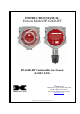
INSTRUCTION MANUAL Detcon Model FP-624D-HT FP-624D-HT Combustible Gas Sensor (0-100% LEL) DETCON, Inc. 4055 Technology Forest Blvd, Suite 100, The Woodlands, Texas 77381 Ph.281.367.4100 / Fax 281.298.2868 www.detcon.com April 23, 2012 • Document #3458 • Revision 1.
Model FP-624D-HT This page left intentionally blank FP-624D-HT Instruction Manual ii
Model FP-624D-HT Table of Contents 1. 2. 3. 4. 5. 6. 7. 8. 9. Introduction............................................................................................................................................ 1 1.1 Description..................................................................................................................................... 1 1.2 Modular Mechanical Design...........................................................................................................
Model FP-624D-HT List of Figures Figure 1 Sensor Assembly Front View............................................................................................................ 1 Figure 2 Sensor Cell Construction .................................................................................................................. 2 Figure 3 Wheatstone Bridge ........................................................................................................................... 2 Figure 4 Response Curves ...
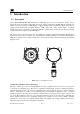
Model FP-624D-HT 1. Introduction 1.1 Description Detcon Model FP-624D-HT High Temperature combustible gas sensors are non-intrusive “Smart” sensors designed to detect and monitor combustible gases in air. Range of detection is 0-100% LEL (Lower Explosive Limit). The sensor features an LED display of current reading, fault, and calibration status. The sensor is equipped with standard analog 4-20mA, ModbusTM RTU output, and 3 relay contact outputs.
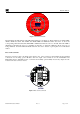
Model FP-624D-HT Alumina Bead Platinum Wire Catalytic Beads Main Housing Insert Catalyst Printed Circuit Board Gold Plated Pins Construction of Detector Bead Figure 2 Sensor Cell Construction Principle of Operation Method of detection is by diffusion/adsorption. Air and combustible gases pass through a sintered stainless steel filter and contact the heated surface of both the active and reference detectors.
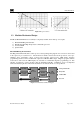
Model FP-624D-HT Figure 4 Response Curves 1.2 Modular Mechanical Design The Model FP-624D-HT Sensor Assembly is completely modular and is made up of four parts: 1) 2) 3) 4) FP-624D-HT Plug-in Transmitter Field Replaceable High Temperature combustible gas sensor Connector PCB Splash Guard FP-624D-HT Plug-in Transmitter The Plug-in Transmitter Module is a microprocessor-based package that plugs into the connector board located in the explosion proof junction box.
Model FP-624D-HT PGM MODEL 1 HOUSTON, TEXAS FP-624D MicroSafeTM LEL Gas Sensor FLT ALM ALM 1 2 CAL PGM 2 Figure 6 Transmitter Module The transmitter module includes four LED status indicators (see Figure 3). These indicators are labeled FLT, ALM1, ALM2 and CAL. The ALM1 and ALM2 LEDs are illuminated when the sensor is above the corresponding alarm threshold. The FLT LED is illuminated when the sensor is in fault.
Model FP-624D-HT 1.3 Relay Outputs The FP-624D-HT includes three 5A Form C relay outputs. Two of these relays are dedicated to alarm outputs, and the third is used to indicate when the sensor is in fault. The common and normally closed contacts on the alarm relays are connected when the gas concentration is below the alarm threshold. If the concentration exceeds the alarm threshold for more than five seconds, then the common and normally open contacts will be connected.
Model FP-624D-HT 2. Installation 2.1 Operational Guidelines for Safe Use 1. Install sensor only in areas with classifications matching with those described on the approval label. Follow all warnings listed on the label. 2. Ensure that the sensor is properly mounted in a vertical orientation with sensor facing down. Avoid use of excessive Teflon Tape, or any type of non-conductive pipe thread coating on the NPT threaded connection. All NPT connections should remain grounded to the junction box. 3.
Model FP-624D-HT Density Placement of sensors relative to the density of the target gas is such that sensors for the detection of heavier than air gases should be located within 4 feet of grade as these heavy gases will tend to settle in low lying areas. For gases lighter than air, sensor placement should be 4-8 feet above grade in open areas or in pitched areas of enclosed spaces. NOTE: Methane and Hydrogen are lighter than air. Most other combustible gases are heavier than air.
Model FP-624D-HT Detcon High Temperature combustible gas sensors may be adversely affected by exposure to certain airborne substances. Loss of sensitivity or corrosion may be gradual if such materials are present in sufficient concentrations. The performance of the detector elements may be temporarily impaired during operation in the presence of substances described as inhibitors. Inhibitors are usually volatile substances containing halogen compounds.
Model FP-624D-HT 4.65" 6.1" 5.5" 3 4 NPT Ports 5.825" 1 4" mounting holes High Temperature LEL Sensor Wall (or other mounting surface) External Ground Screw 8-32 x 5/16" binding head screw 2.1" Splash Guard 2" 0.5" Figure 8 Typical Outline and Mounting Dimensions 2.5 Electrical Installation The Sensor Assembly should be installed in accordance with local electrical codes. The sensor assemblies are CSA/NRTL approved (US and Canada) for Class I, Division 1, Groups B C D area classifications.
Model FP-624D-HT Conduit "T" EYS Seal Fitting Drain Figure 9 Typical Installation NOTE: Any unused ports should be blocked with suitable ¾” male NPT plugs. Detcon Supplies one ¾” NPT male plug with each J-box enclosure. If connections are other than ¾” NPT, use an appropriate male plug of like construction material. 2.6 Field Wiring Detcon Model FP-624D-HT High Temperature combustible gas sensor assemblies require up to five conductor connections between power supplies and host electronic controller.
Model FP-624D-HT Terminal Connections Alarm 1 Alarm 2 Fault CAUTION: Do not apply System power to the sensor until all wiring is properly terminated. Refer to Section 2.8 Initial Start Up Customer Wiring Power (+ -) 4-20 mA White Black Yellow Blue RS-485 (A,B) Wiring to LEL Sensor Figure 10 Sensor Connector PCB a) Remove the junction box cover and unplug the Transmitter Module. Identify the terminal blocks for customer wire connections.
Model FP-624D-HT AWG 20 18 16 14 Maximum Separation (feet) 50 75 125 175 Reference Figure 11 for wiring diagram. Also note the jumper that is required on the remote sensor connector board. Failure to install this jumper will cause a sensor fault condition. Figure 11 Remote Sensor Wiring Diagram 2.7.1 Bridge Voltage Adjustment When a sensor is remote mounted, consideration must be given to the lengths of cable used and how it affects the sensor bridge voltage.
Model FP-624D-HT -Detcon PN 600-610000-000 Splash Guard with integral Cal Port -OR-Detcon PN 943-000006-038 Threaded Calibration Adapter - Detcon PN 942-520124-050 Span Gas; 50% LEL methane/balance Air at fixed flow rate of 200-500cc/min. NOTE: Do not use calibration gases in Nitrogen background gas mixtures. This will cause significant reading inaccuracies. a) Attach the calibration adapter to the threaded sensor housing.
Model FP-624D-HT 3. Operation 3.1 Programming Magnet Operating Instructions The Operator Interface of the FP-624D-HT gas sensors is accomplished via two internal magnetic switches located above and below the LED display (Figure 13). The two switches, labeled “PGM1” and “PGM2”, allow for complete calibration and configuration, thereby eliminating the need for area de-classification or the use of hot permits.
Model FP-624D-HT 3.2 Operator Interface The operating interface is menu-driven via the two magnetic program switches located under the target marks of the sensor housing. The two switches are referred to as “PGM1” and “PGM2”. The menu list consists of three major items that include sub-menus as indicated below. (Refer to the complete Software Flow Chart.
Model FP-624D-HT Software Flowchart Normal Operation PGM1 (3) PGM2 (3) PGM1 (3) PGM2 (3) Calibration Mode (Auto Zero) Calibration Mode (Auto Span) View Sensor Status Auto Time-Out PGM1/2 (M) PGM1/2 (3) Set AutoSpan Level Set Gas Factor Auto Time-Out PGM1/2 (M) PGM1/2 (3) AutoTime-out PGM1/2 (M) PGM1/2 (3) Set Bridge Voltage Set Cal Factor Auto Time-Out PGM1/2 (M) PGM1/2 (3) Auto Time-Out PGM1/2 (M) PGM1/2 (3) Model Type Version X.
Model FP-624D-HT 3.3 Normal Operation In normal operation, the display continuously shows the current sensor reading, which will normally appear as “0”. Once every minute, the LED display will flash the sensor’s units of measure and the gas type (i.e. % LEL). If the sensor is actively experiencing any diagnostic faults, a “Fault Detected” message will scroll across the display once every minute instead of the units of measure and the gas type.
Model FP-624D-HT c) The transmitter will display the following sequence of text messages as it proceeds through the AutoZero sequence: Zero Cal . . . Setting Zero . . . Zero Saved (each will scroll twice) d) Remove the zero gas and calibration adapter, if applicable. 3.4.
Model FP-624D-HT Fault Status register will be set until the calibration is complete. c) Apply the span calibration test gas at a flow rate of 200-500cc/min (200cc/min is the recommended flow rate). As the sensor signal begins to increase, the display will switch to reporting a flashing “XX” reading as the display shows the sensor’s “as found” response to the span gas presented.
Model FP-624D-HT The Program Mode menu items appear in the order presented below: View Sensor Status Set AutoSpan Level Set Gas Factor Set Cal Factor Set Bridge Voltage Signal Output Check Restore Default Settings Set Serial ID Alarm 1 Settings Alarm 2 Settings Fault Settings Navigating Program Mode From Normal Operation, enter Program Mode by holding the magnet over PGM2 for 4 seconds (until the displays starts to scroll “View Sensor Status”).
Model FP-624D-HT AutoSpan Level The menu item appears as: “Auto Span Level XX” Days Since Last AutoSpan The menu items appears as: “Last Cal XX days” Remaining Sensor Life The menu item appears as: “Sensor Life XXX%” Sensor Bridge Current The menu item appears as: “Bridge XXXmA” Sensor Bridge Voltage The menu item appears as: “Bridge X.XXVDC Gas Factor The menu item appears as: “Gas Factor X.XX” Cal Factor The menu item appears as: “Cal Factor X.XX” mA Output The menu item appears as: “mA Output XX.
Model FP-624D-HT Alarm 2 Level The menu item appears as: “Alarm 2 Level XX” Alarm 2 Ascending The menu item appears as: “Alarm 2 Ascending or Descending” Alarm 2 Latching The menu item appears as: “Alarm 2 Latching or Non-Latching” Alarm 2 Energized The menu item appears as: “Alarm 2 Energized or Non-Energized” Fault Latching The menu item appears as: “Fault Latching or Non-Latching” Fault Energized The menu item appears as: “Fault Energized or Non-Energized” When the status list sequence is complete, the
Model FP-624D-HT NOTE: The default value for gas factor is 1.0. This would be used when methane is the target gas. Values other than 1.0 would be used when the target gas is not methane. Set Gas Factor is used to make the appropriate signal sensitivity adjustment when the target gas is a gas other than methane. This is necessary because the catalytic bead sensor has different signal strengths for each combustible gas and all reading calculations are made based on a reference to methane.
Model FP-624D-HT The menu item appears as: “Set Gas Factor”. From the Set Gas Factor text scroll, hold the magnet over PGM1 or PGM2 until the “▼” prompt appears and continue to hold the magnet in place for an additional 3-4 seconds (until the display starts to scroll “Set Factor”). The display will then switch to “X.XX“(where X.XX is the current gas factor). Swipe the magnet momentarily over PGM1 to increase or PGM2 to decrease the gas factor level until the correct value is displayed.
Model FP-624D-HT it is notably better than sensors that are operated on a common fixed bridge voltage platform. The range of bridge voltages required for Detcon sensors is generally between 2.5 – 2.9VDC. NOTE: The “Set Bridge Voltage” function is executed during factory calibration of every FP624D-HT sensor.
Model FP-624D-HT NOTE: “Restoring Factory Defaults” should only be used when absolutely necessary. All previously existing configuration inputs will have to be re-entered if this function is executed. A full 10-second magnet hold on PGM 1 is required to execute this function. From the “Restore Defaults” text scroll, hold the programming magnet over PGM1 until the “▲” prompt appears and continue to hold 10 seconds.
Model FP-624D-HT 3.5.9 Alarm 1 and 2 Settings The FP-624D-HT contains two Form C alarm relay outputs. These relays can be configured to change state when the concentration exceeds a set level. The relays can be configured to operate in either energized or nonenergized mode. In non-energized mode, the normally open contact is open if the alarm level has not been reached. In energized mode, the normally open contact is closed if the alarm level has not been reached.
Model FP-624D-HT The fault relay can be configured as either latching or non-latching. In non-latching mode, the relay is deactivated as soon as the fault condition is cleared. In latching mode, the relay remains active even after the fault condition has cleared. Once activated, the relay can only be deactivated by swiping a magnetic programming tool above the PGM1 or PGM2 mark on the FP-624D-HT face plate.
Model FP-624D-HT Last AutoSpan Date This reports the number of days that have elapsed since the last successful AutoSpan. This is reported in the View Sensor Status menu. After 180 days, an AutoSpan Fault will be declared. 3.6.2 Fault Diagnostic/Failsafe Features Fail-Safe/Fault Supervision Model FP-624D-HT MicroSafe™ sensors are designed for Fail-Safe operation.
Model FP-624D-HT Sensor Voltage Fault If the voltage across the sensor bridge (See Figure 3) is greater than 3.5VDC or less than 1.8VDC, a “Sensor Voltage Fault” will be declared. A “Sensor Voltage Fault” will cause a “Fault Detected” message to scroll once a minute on the transmitter display. If a Sensor Voltage Fault occurs, the 4-20mA signal will be set at 0mA and the “Sensor Voltage Fault” bit will be set until the fault condition is resolved.
Model FP-624D-HT 4. RS-485 ModbusTM Protocol Model FP-624D-HT sensors feature Modbus™ compatible communications protocol output and are addressable via the program mode. Communication is via a two wire, half duplex RS-485, 9600 baud, 8 data bits, 1 stop bit, no parity, with the sensor set up as a slave device. A master controller up to 4000 feet away can poll up to 256 different FP-624D-HT sensors.
Model FP-624D-HT 03/ 40014 06 Special #4 R/W 03 40015 Calibration Status R 06 40015 Calibration Enable W 03 03 03 03 03 03 03 Function Dependant on Value of 40006 (See Special Register Table) Idle Zero Calibration Started Span Calibration Started Span Set Span Calibration Unsuccessful Set Zero Set Span Signal simulation mode Set FP Bridge Voltage Set TP Heater Power Set IR Gain Two Char of Gas/Units String6 Two Char of Gas/Units String6 Two Char of Gas/Units String6 Two Char of Gas/Units String6 T
Model FP-624D-HT 5. Service and Maintenance Calibration Frequency In most applications, monthly to quarterly span calibration intervals will assure reliable detection. However, industrial environments differ. Upon initial installation and commissioning, close frequency tests should be performed, weekly to monthly. Test results should be recorded and reviewed to determine a suitable calibration interval.
Model FP-624D-HT Replacement of the Connector PCB NOTE: It is necessary to remove power to the junction box while changing the connector PCB in order to maintain area classification. a) Remove the junction box cover and remove the transmitter module from the connector PCB. b) Remove the red green and blue wires coming from the High Temperature combustible gas sensor from the connector PCB. c) Remove the output wiring from the connector PCB terminals.
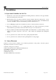
Model FP-624D-HT 6. Troubleshooting Guide Refer to the list of Failsafe Diagnostic features listed in Section 3.6.2 for additional reference in troubleshooting activities. Listed below are some typical trouble conditions and their probable cause and resolution path. Figure 15 Replaceable High Temperature Combustible Gas Sensor Sensor Current/Voltage Fault Probable Causes: Open Sensor – broken wire or contact in sensor Remove sensor and check red wire against green wire, then blue wire against green wire.
Model FP-624D-HT Probable Causes: Failed sensor, cal gas not removed at appropriate time, problems with cal gas and delivery, or background combustible gases preventing clearing Confirm that no combustible gasses are present in background. Check bridge voltage (should be 2.7 +/- 0.2VDC). Check validity of span gas and flow rate (check MFG date on cal cylinder). Make sure correct cal factor and gas factor is set Check for obstructions through stainless steel sinter element (including being wet).
Model FP-624D-HT Processor and/or Memory Faults Recycle power in attempt to clear problem Restore factory defaults - This will clear the processor’s memory and may correct problem. Remember to reenter all customer settings for range and cal gas level after Restore Factory Defaults. If problem persists, replace the plug-in transmitter module. Unreadable Display If due to excessive sunlight, install a sunshade to reduce glare.
Model FP-624D-HT 7. Customer Support and Service Policy Detcon Headquarters Shipping Address: 4055 Technology Forest Blvd, Suite 100, The Woodlands Texas 77381 Mailing Address: P.O. Box 8067, The Woodlands Texas 77387-8067 Phone: 888.367.4286, or 281.367.4100 Fax: 281.292.2860 • www.detcon.com • service@detcon.com • sales@detcon.com All Technical Service and Repair activities should be handled by the Detcon Service Department via phone, fax or email at contact information given above.
Model FP-624D-HT 8. FP-624D-HT Sensor Warranty High Temperature combustible gas sensor Warranty Detcon Inc. warrants, under normal intended use, each LEL High Temperature Sensor Assembly (p/n 365037020-16H) for a two year period under conditions described as follows: The warranty period begins on the date of shipment to the original purchaser and ends 2 years thereafter. The sensor element is warranted free of defects in material and workmanship.
Model FP-624D-HT 9. Appendix 9.
Model FP-624D-HT Status Indicators: 4-digit LED Display with gas concentration, full-script menu Prompts for AutoSpan, AutoZero, Set-up Options, and Fault Reporting Faults Monitored: Loop Fault, Input Voltage Fault, Zero Fault, Sensor Fault, Processor Fault, Memory Fault, Calibration Fault(s) 4 LEDs for Alarm 1, Alarm 2, Fault, and Calibration Cable Requirements: Power/Analog: 3-wire shielded cable Maximum distance is 13,300 feet with 14 AWG Serial Output: 2-wire twisted-pair shielded cable specified
Model FP-624D-HT 9.
Model FP-624D-HT 9.3 Revision Log Revision 0.0 0.1 1.0 1.1 Date 5/18/2010 5/18/2010 1/16/2012 04/23/12 FP-624D-HT Instruction Manual Changes made Initial Release Updated K factor table Updated to FP-624D transmitter Updated Section 2.6 Field Wiring, load resistor Rev. 1.
Model FP-624D-HT This page left intentionally blank Shipping Address: 4055 Technology Forest Blvd, Suite 100, The Woodlands Texas 77381 Mailing Address: P.O. Box 8067, The Woodlands Texas 77387-8067 Phone: 888.367.4286, 281.367.4100 • Fax: 281.292.2860 • www.detcon.com • sales@detcon.com FP-624D-HT Instruction Manual Rev. 1.