Detcon MicroSafe™ Model DM-534C Oxygen Deficiency Sensor (0-25% O2) Operator’s Installation and Instruction Manual DETCON, Inc. 4055 Technology Forest Blvd, Suite 100, The Woodlands, Texas 77381 Ph.281.367.4100 / Fax 281.298.2868 www.detcon.com February 21,2012 • Document #2405 • Revision 1.
DM-534C Oxygen Sensor Assembly This page left intentionally blank DM-534C O2 Sensor Instruction Manual ii
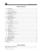
DM-534C Oxygen Sensor Assembly Table of Contents 1.0 DESCRIPTION........................................................................................................................................ 1 1.1 Sensor Technology ............................................................................................................................... 1 1.2 Base Connector Board.......................................................................................................................... 2 1.
DM-534C Oxygen Sensor Assembly Figure 4 Explosion proof enclosures................................................................................................................. 3 Figure 5 Functional Block Diagram .................................................................................................................. 3 Figure 6 Typical Installation .............................................................................................................................
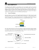
DM-534C Oxygen Sensor Assembly 1.0 DESCRIPTION Detcon MicroSafe™ Model DM534C, oxygen deficiency sensors are non-intrusive “Smart” sensors designed to detect and monitor O2 in air over the range of 0-25%. One of the primary features of the sensor is its method of automatic calibration which guides the user through each step via instructions displayed on the backlit LCD. The sensor output is a standard 4-20 mA signal.
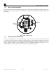
DM-534C Oxygen Sensor Assembly 1.2 Base Connector Board The base connector board is mounted in the explosion proof enclosure and includes: the mating connector for the control circuit, reverse input and secondary transient suppression, input filter, and lugless terminals for field wiring. Wiring to O2 Sensor Customer Wiring Figure 3 Base connector board 1.3 Explosion Proof Enclosure The sensors are packaged in a cast metal explosion proof enclosure.
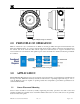
DM-534C Oxygen Sensor Assembly Figure 4 Explosion proof enclosures 2.0 PRINCIPLE OF OPERATION Method of detection is by a controlled rate of diffusion. Air and gas diffuse through a sintered stainless steel filter and a diffusion barrier. As oxygen is adsorbed into the electrolyte solution a current is generated between the cathode and anode electrodes. This current output rises with increases in oxygen concentration and reverses with lower concentrations.
DM-534C Oxygen Sensor Assembly 3.2 Interference Data Table 1 Interference Data Methane Hydrocarbons Hydrogen Carbon Monoxide 4.0 100% = 0 100% = 0 100% = < 2% 20% = < 0.5% SPECIFICATIONS Method of Detection Air battery diffusion/adsorption Electrical Classification Class I; Groups B, C, D; Div. 1. Response Time (T90) T90 < 20 seconds Clearing Time 90% < 20 seconds Repeatability ± 2% FS Range 0-25% O2 Operating Temperature -4° to +122° F Accuracy ± 2% FS Linearity ± 0.
DM-534C Oxygen Sensor Assembly 5.1 Normal Operation In normal operation, the display tracks the current status of the sensor and gas concentration and appears as: “20.9 % O2”" The mA current output corresponds to the monitoring level of 0-25% O2 = 4-20 mA. 5.2 Calibration Mode Calibration mode allows for sensor zero and span adjustments. “2 - SPAN” The default span adjustment is set at 20.9% which is the normal atmospheric concentration of O2. Span gas concentrations other than 20.9 % may be used.
DM-534C Oxygen Sensor Assembly The RS485 (if applicable) requires 24 gauge, two conductor, shielded, twisted pair cable between sensor and host PC. Use Belden part number 9841. Two sets of terminals are located on the connector board to facilitate serial loop wiring from sensor to sensor. Wiring designators are A & B (IN) and A & B (OUT). 6.2 Sensor Location Selection of sensor location is critical to the overall safe performance of the product.
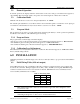
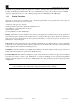
DM-534C Oxygen Sensor Assembly Conduit "T" EYS Seal Fitting PGM MODEL 1 HOUSTON, TEXAS DM-534C MicroSafeTM O2 Gas Sensor Drain ALM ALM FLT PGM CAL 2 Figure 6 Typical Installation 6.3 Local Electrical Codes Sensor and transmitter assemblies should be installed in accordance with all local electrical codes. Use appropriate conduit seals. Drains & breathers are recommended. The sensor assemblies are designed to meet NEC and CSA requirements for Class I; Groups B, C, D; Div. 1 environments. 6.
DM-534C Oxygen Sensor Assembly 3/4" NPT Ports 4.65" 6.1" 5.5" 8-32 tapped ground point Wall (or other mounting surface 5.825" 7.92" 1/4" Mounting holes O2 Sensor Splash Guard 2" Cal Port 0.5" Figure 7 Typical Outline and Mounting Dimensions c) Observing correct polarity, terminate 3-conductor field wiring to the sensor base connector board in accordance with the detail shown in Figure 8. d) Replace the plug-in transmitter circuit and replace the junction box cover.
DM-534C Oxygen Sensor Assembly Remote Transmitter DM-534C-RT Remote Sensor DM-534C-RS Blue White Blue White Figure 9 Remote mounting application 7.0 START UP Upon completion of all mechanical mounting and termination of all field wiring, apply system power and observe the following normal conditions a) “Fault” LED is off. b) A temporary upscale reading may occur as the sensor powers up. This upscale reading will clear to about 20.
DM-534C Oxygen Sensor Assembly b) b) Remove the test gas and observe that the LCD display increases back to 20.9% ±2% of scale (0.5% O2). c) Initial operational tests are complete. Detcon O2 gas sensors are pre-calibrated prior to shipment and will, in most cases, not require significant adjustment on start up. However, it is recommended that a complete calibration test and adjustment be performed within 24 hours of installation. Refer to calibration instructions in section 8.0. 8.
DM-534C Oxygen Sensor Assembly NOTE: If, after entering the calibration or program menus, there is no interaction with the menu items for more than 30 seconds, the sensor will return to its normal operating condition . 8.1 Calibration Procedure - Span NOTE 1: Before performing an ambient air O2 span calibration, be sure there is no oxygen deficient condition present.
DM-534C Oxygen Sensor Assembly NOTE 1: If the circuitry is unable to adjust the span to the proper setting the sensor will enter into the calibration fault mode which will cause the display to alternate between the sensor’s current status reading and the calibration fault screen which appears as: “CAL FAULT” (see section 3.7.3).. 8.2 Additional Notes 1. Upon entering the calibration menu, the 4-20 mA signal drops to 2 mA and is held at this level until you return to normal operation. 2.
DM-534C Oxygen Sensor Assembly g) From the calibration menu “2- SPAN” (section 8.1) proceed into the span adjust function by holding the programming magnet stationary over “PGM 2” for 3 seconds until the display reads “APPLY xx.x% O2” then withdraw the programming magnet. The x’s here indicating the gas concentration requested. h) Apply the calibration gas at a flow rate of 500 milliliters per minute. As the sensor signal changes, the display will change to “SPAN xx.x%”. The “xx.
DM-534C Oxygen Sensor Assembly Detcon MicroSafe™ sensors are programmed for failsafe operation. Any of the following fault condition will illuminate the fault LED, and cause the display to read its corresponding fault condition: “SENSOR FAULT”, or “CAL FAULT”. A “Sensor Fault” will also cause the mA output to drop to zero (0) mA. Sensor Life The sensor life feature is a reference based on signal output from the sensor cell.
DM-534C Oxygen Sensor Assembly 9.0 TROUBLE SHOOTING Memory or Error Reports 1. Reinitialize Sensor Unplug transmitter and replug transmitter then swipe magnet over PGM 1 in the first 3 seconds. This will clear the processor and recover from error state. Remember to put in all customer settings for range, alarm and cal gas level after re-initialization. Non-readable Display 1. If display has blue background when hot, install sunshade to reduce temperature. 2.
DM-534C Oxygen Sensor Assembly 10.0 SPARE PARTS LIST 600-610000-000 943-000006-132 500-005065-007 327-000000-000 897-850902-010 960-202200-000 370-399100-000 925-345400-025 399-200000000 Sensor splash guard Calibration Adapter for FP, IR, DM and O2 Sensors Connector board Programming Magnet Detcon Alum Condulet w/Window Cover Condensation prevention packet (replace annually).
DM-534C Oxygen Sensor Assembly 11.0 WARRANTY Detcon, Inc., as manufacturer, warrants each new plug-in O2 sensor cell (PN 370-399100-000), for a two year period under the conditions described as follows: The warranty period begins on the date of shipment to the original purchaser and ends two years thereafter. The sensor cell is warranted to be free from defects in material and workmanship.
DM-534C Oxygen Sensor Assembly Appendix C Revision History Revision 1.3 1.4 Date 02/05/10 02/21/12 Changes made Last release Removed section Calibration- Zero Span. Corrected Spare Parts List (section 10.0). Added Revision history. Converted to Word format Approvals BM BM Shipping Address: 4055 technology Forest Blvd, Suite 100., The Woodlands Texas 77381 Mailing Address: P.O. Box 8067, The Woodlands Texas 77387-8067 Phone: 888.367.4286, 281.367.4100 • Fax: 281.292.2860 • www.detcon.com • sales@detcon.