
User Manual

1640-N4X
1640-N4X Instruction Manual iii
Table of Contents
1.0
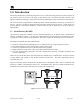
Introduction .............................................................................................................................................1
1.1 Serial Sensors (RS-485) ....................................................................................................................... 1
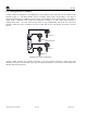
1.2 Analog Sensors (4-20mA).................................................................................................................... 2
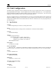
2.0 Unit Configuration ..................................................................................................................................3
2.1 Specifications ....................................................................................................................................... 3
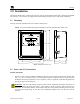
3.0 Installation ...............................................................................................................................................5
3.1 Mounting .............................................................................................................................................. 5
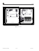
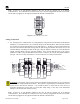
3.2 Power and I/O Connections.................................................................................................................. 5
3.3 Initial Power Checks ............................................................................................................................ 8
4.0 Setup .........................................................................................................................................................9
4.1 Front Panel User Interface.................................................................................................................... 9
4.2 Main Menu ........................................................................................................................................... 9
4.2.1 Set Number of Channels ................................................................................................................................10
4.2.2 Set Com 1 Baud Rate..................................................................................................................................... 10
4.2.3 Set Com 2 Baud Rate..................................................................................................................................... 11
4.2.4 Setup Channel Data........................................................................................................................................ 11
4.2.5 Set Channel Alarms ....................................................................................................................................... 13
4.2.6 Set Relay Function......................................................................................................................................... 14
4.2.7 Set Modbus™ Address .................................................................................................................................. 15
4.2.8 Calibration Mode ........................................................................................................................................... 15
4.2.9 System Diagnostics........................................................................................................................................ 16
4.3 Display Contrast ................................................................................................................................. 16
4.4 Reset Switch ....................................................................................................................................... 16
5.0 Modbus™ Communications.................................................................................................................17
6.0 Trouble-shooting ...................................................................................................................................18
6.1 Sensor Faults ...................................................................................................................................... 18
6.2 Troubleshooting RS485 Networks ..................................................................................................... 18
7.0 Warranty................................................................................................................................................19
Appendix A ........................................................................................................................................................20
RS-485 Unit Integration Wiring..................................................................................................................... 20
Appendix B ........................................................................................................................................................26
Hexadecimal Table......................................................................................................................................... 26
Appendix C ........................................................................................................................................................27
Drawings and Diagrams ..................................................................................Error! Bookmark not defined.
Table of Figures
Figure 1 RS-485 Network Configuration............................................................................................................. 1
Figure 2 DA4 4-20mA Configuration .................................................................................................................. 2
Figure 3 Unit Overview........................................................................................................................................ 4
Figure 4 Dimensional Overview .......................................................................................................................... 5
Figure 5 Typical RS-485 connections.................................................................................................................. 6
Figure 6 Typical Analog Sensor Wiring .............................................................................................................. 7