
User Manual

1640-N4X
1640-N4X Instruction Manual Rev. 0.0 Page 8 of 28
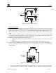
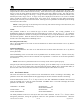
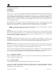
(Alarm 1). Each relay has a set of dry contacts labeled “COM” Common, “NC” Normally Closed, and
“NO” Normally Open (Figure 9). Wire annunciators to the appropriate alarm/fault relay.
FAULT ALM3 ALM2 ALM1
NC NO NC NO NC NO NC NO
Upper left of Controller PCA
Figure 9 Alarm Relay Connections
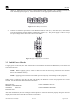
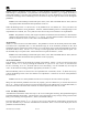
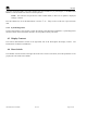
4. Connect 110-220VAC input to the Circuit Breakers labeled “VAC (L1)” and “NEU (L2)” and Ground
to the Green/Yellow terminal labeled “GROUND” (Figure 10). The power supply is able to accept
AC input voltages from 100 to 240 volts at 50 or 60Hz.
O
I
5A
O
I
5A
GROUND
VAC (L1)
NEU (L2)
Figure 10 Typical Input Power connections
3.3 Initial Power Checks
To apply power to the unit, turn “ON” both of the Circuit breakers located on the Back Panel, in the lower left
side of the enclosure.
NOTE: Before applying power, check to make sure that all the wiring connections and external
devices are installed correctly.
NOTE: Applying power with devices hooked up incorrectly may cause damage to the equipment.
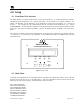
When power is applied to the unit, the unit will display the firmware revision and properties for several
seconds. For this controller that information should be:
DETCON INC COM 1 MODBUS SLAVE
MODBUS CONTROLLER
VERSION XX.XXX COM 2 MODBUS MASTER
PCWH X.XXX
After unit initialization, the unit will begin normal operation. If the unit has been properly setup, the unit will
display the current status of the devices that are connected to.