Model 1640-N4X Gas Detection Unit Model 1640-N4X Gas Detection / Alarm System Operator’s Installation and Instruction Manual DETCON, Inc. 3200 Research Forest Dr., A-1 The Woodlands, Texas 77381 Ph.281.367.4100 / Fax 281.298.2868 www.detcon.com August 25, 2009 • Document # 3312 • Revision 0.
1640-N4X Page intentionally blank Shipping Address: 3200 A-1 Research Forest Dr., The Woodlands Texas 77381 Mailing Address: P.O. Box 8067, The Woodlands Texas 77387-8067 Phone: 888.367.4286, 281.367.4100 • Fax: 281.292.2860 • www.detcon.com • sales@detcon.
1640-N4X Table of Contents 1.0 1.1 1.2 2.0 2.1 3.0 3.1 3.2 3.3 4.0 4.1 4.2 Introduction .............................................................................................................................................1 Serial Sensors (RS-485) ....................................................................................................................... 1 Analog Sensors (4-20mA)..............................................................................................................
1640-N4X Figure 7 Alarm Relay Connections ...................................................................................................................... 8 Figure 8 Typical Input Power connections........................................................................................................... 8 Figure 9 Front Panel .............................................................................................................................................
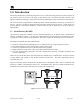
1640-N4X 1.0 Introduction The Detcon Model 1640 is specifically designed to serve as a host monitoring and control unit for networks of gas detection sensors as well as a wide range of other field devices. The NEMA 4X rated enclosure is rain tight and suitable for mounting in outdoor locations that are deemed electrically non-hazardous environments. The 1640 Controller is programmed as a Modbus™ master with the capabilities to monitor up to 32 Sensors or Devices.
1640-N4X 1.2 Analog Sensors (4-20mA) Another method of integration is accomplished by using 4-20mA signal output devices with Detcon DA4 Modules (Figure 2). The DA4 Module receives a 4-20mA analog signal corresponding to the range of detection then changes it to Modbus™ before relaying the information to the 1640 Controller. The Sensor’s output signal is calibrated so that a 4mA input represents a reading of “0” and a 20mA input represents a reading of full scale.
1640-N4X 2.0 Unit Configuration The Model 1640 is designed to monitor and display the status of up to 32 field sensor devices, provide power, and programmable alarm outputs. The unit displays real time channel information on a 1” X 5” backlit LCD. Display information includes the channel number, the gas type, and the gas concentration. The unit will also display the current Alarm/Fault status via the front panel LED indicators.
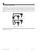
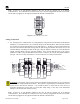
1640-N4X Alarm Relay Terminals FAULT NC NO ALARM3 ALARM2 ALARM1 NC NO NC NO ACV IN NC NO E L2 L1 VDC IN + Power Supply Ground S 1640 Controller PCA COM 1 B A Alarm Reset Switch S COM 2 B A COMM 5A I 5A O COMM COMM COMM COMM COMM M S D M S D M S D M S D M S D M S D M S D L S D L S D L S D L S D L S D L S D L S D L S D 4-20mA INPUT 4-20mA INPUT 4-20mA INPUT 4-20mA INPUT 4-20mA INPUT 4-20mA INPUT 4-20mA INPUT + A B VAC (L1) NEU (L2) GROUND COMM M S D 4-20m
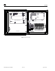
1640-N4X 3.0 Installation The Detcon Model 1640 s a wall-mount enclosure, and can be mounted anywhere that is rated safe for NEMA 4X enclosures. The enclosure is equipped with wall-mounting brackets for easy wall mount installations. 3.1 Mounting Securely mount the 1640 Enclosure in accordance with Figure 4. NOTE: AC power should be kept separate from DC power and signals within conduit runs. Model 1640-N4X Gas Detection / Alarm System 14.75" 15.75" 10" Mounting Flanges 13.85" 6.5" 6.
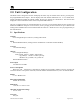
1640-N4X + A B Note: If there are no I/O Modules installed in the unit, J2 must be plugged into J1 for RS-485 Communication. If I/O Modules are installed in the unit J1 must be plugged into the left most module, and J2 must be plugged into the right most module for RS-485 Communication. RS-485 VDC Primary Out Figure 5 Typical RS-485 connections Analog Connections 2. For Analog Sensors, communication is accomplished by using Detcon DA4 modules and the RS-485 Modbus™.
1640-N4X Sensor 4 RS-485 to 1640 COMM Sensor 3 Typical Sensors M S D L S D 4-20mA INPUT Sensor 1 Sensor 2 Figure 7 Typical Analog Sensor Wiring General Wiring Notes: When I/O Modules are located at a remote distance from the controller, an end-of-line terminating resistor is required to enhance communications reliability. Identify the last I/O Module in the loop, and open the module casing using the clip release points. Locate and install the jumper on JP6 (TERM) Figure 8.
1640-N4X (Alarm 1). Each relay has a set of dry contacts labeled “COM” Common, “NC” Normally Closed, and “NO” Normally Open (Figure 9). Wire annunciators to the appropriate alarm/fault relay. FAULT NC NO ALM3 NC NO ALM2 NC NO ALM1 NC NO Upper left of Controller PCA Figure 9 Alarm Relay Connections 4. Connect 110-220VAC input to the Circuit Breakers labeled “VAC (L1)” and “NEU (L2)” and Ground to the Green/Yellow terminal labeled “GROUND” (Figure 10).
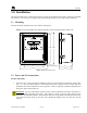
1640-N4X 4.0 Setup 4.1 Front Panel User Interface The Main Display is a backlit LCD that has 4 lines by 40 characters. In normal operation the channel’s information will be displayed as “01> XXXX ppm GAS”. If any channel is in an alarm condition, “01> XXXX IN ALARM ” will be displayed. If any channels are in Fault, they will display “01> XXXX IN FAULT ”. Any channels are not communicating with the controller will be displayed as “01> XXXX COMM ERROR ”.
1640-N4X SYSTEM DIAGNOSTICS The “PROG” key is used to enter the Menu Mode of the unit. Upon entering the Main Menu the LCD will display: MAIN MENU SET # OF CHANNELS Use the “v” (Down Arrow) key to move to the next menu item, or use the “u” (Up Arrow) key to move to the previous menu item. When the appropriate Menu Item is displayed, use the “ENTER” Key to enter that menu item. Pressing the “PROG” key again will return the unit to normal operation.
1640-N4X 4.2.3 Set Com 2 Baud Rate The “SET COM3 BAUD RATE” menu allows setting the communications baud rate for communications port 2. The Baud rate can be set to 4800, 9600, 14400, or 19200. The normal Baud rate is set to 9600 Baud, and should not be changed. From the Main Menu use the “u” or “v” keys to move to the “SET COM2 BAUD RATE” menu item and press “ENTER” to enter the “SET COM2 BAUN RATE” menu. The display will change to “BAUD RATE COM 2:” followed by the current Baud Rate setting.
40-N4X REGS TO READ (Registers to read): This is pre-programmed to the value of 6 and should not be altered unless directed to do so by Detcon Factory Personnel. READING REG (Reading Register): This is pre-programmed to the value of 2 and should not be altered unless using a DA4 Module to monitor analog 4-20mA devices (such as analog sensors). When using a DA4, this parameter must be modified to reflect the sensor to the associated DA4 Module.
1640-N4X displayed on the device as 1.00 should be entered as 2 decimal points, with 1.00 entered as the range. This will provide the correct readout if entered correctly. If the device has a range of 5PPM and is displayed on the device as 5.00, the range should be entered as 2 decimal points with a Range of 5.00. This will provide a reading of 5.00 on the display as the range. A range of 50 that is displayed as 50.0 should be entered as one decimal point and a range of 50.0.
1640-N4X Blinking Cursor is positioned over the colon (“:”) of the parameter to be changed, use the “ENTER” key to make changes to the parameter. The parameter will be displayed in brackets “[ ]” to signify the ability to change that parameter. Once the correct parameter has been set, use the “ENTER” key to accept the change. The Cursor will change back to a Blinking Cursor, and the arrow keys can again be used to move through the parameters.
1640-N4X FAULT RELAY SETUP LATCHING:Y ENERGIZED:Y SILENCABLE:Y Use the “u” or “v” keys to move through the parameters, setting the appropriate values for each parameter as described below. When the Blinking Cursor is positioned over the colon (“:”) of the parameter to be changed, use the “ENTER” key to make changes to the parameter. The parameter will be displayed in brackets “[ ]” to signify the ability to change that parameter.
1640-N4X The relays and alarm LED’s will remain disabled until the “ENTER” key is pressed again, “CALIBRATION MODE” is exited, and the unit returns to normal operation. NOTE: The 1640 does not poll devices while in Menu Mode, so there are no updates to displayed readings or alarms. Press the “PROG” key to exit the Main Manu, or use the “u” or “v” keys to move to the next or previous menu item. 4.2.
1640-N4X 5.0 Modbus™ Communications The 1640 Controller features a Modbus compatible communications protocol and is addressable by a PLC, PC/HMI, DCS, or other Modbus RTU master-polling devices. Communication is accomplished by two wire half duplex RS-485, 9600 baud, 8 data bits, 1 stop bit, no parity, through the controller COM1 connection port (P3). The Slave ID number is defaulted to 01Hex. Modbus™ Register Detail: Code 03 - Read Holding Registers, is the only code supported by the 1640.
1640-N4X 6.0 Trouble-shooting 6.1 Sensor Faults The unit is set up such that Sensor faults will set Fault alarms associated with that sensor. If a sensor goes into a fault condition, that channel will flag a fault. From the “Main Screen” each channel can be quickly viewed to see which channel is causing the fault. That sensor should be then checked to find the cause of the fault. Faults are logged in the Alarm History for aid in tracing intermittent sensor problems.
1640-N4X Measuring at the master device between dc common and A, or dc common and B should give a reading of around 2.5vdc. Remember this is with the power on, but with no communication taking place. Another method of troubleshooting is to enable the communications and remove all the slaves. Proceed to plug 1 slave in and see if communication is good. If so, plug in the next slave and check again.
1640-N4X Appendix A RS-485 Unit Integration Wiring RS-485 is a generic electrical specification only. It does not specify connector types, protocols, or cable type. It is the responsibility of the installer to provide a correct physical installation for the RS-485 network to function properly. RS-485 is very inexpensive and inherently rugged, allowing multiple devices to communicate over a single twisted pair of wires.
1640-N4X The characteristic impedance of the cable must be between 100 to 120 ohms. Twisted pair is used because if the cable does run near a noise source both conductors will pick up the same amount of noise; therefore, effectively canceling it out. Incorrect Wiring Schemes Among the biggest problems with an RS-485 bus is the use of incorrect wiring schemes mixed with improper or no line termination.
1640-N4X Figure 14 Recommended RS-485 communications set-up Grounding Another problem that can occur with RS-485 is incorrect grounding. Neither one of the two conductors in the cable is ground. Both of the conductors are supplying a current to maintain a voltage level relative to an external reference. A third conductor must be supplied to establish a reference through earth ground. RS-485 is specified be able to work normally with a ±7V ground potential difference and survive ±25V surges.
1640-N4X Figure 15 Unbalanced Data Bus The addition of 2 repeaters (Figure 16) can solve this problem. The repeaters look like short stubs to the main bus, and at the same time they create 2 new buses that have all the same characteristics as the main bus. Each leg must have termination resistors to balance the new data bus. Figure 16 Data Bus using two repeaters Be sure to check the equipment being installed.
1640-N4X Device Hook-Up Installation should begin by deciding where devices will be located and how the connections between devices and the master will be established. The ideal scenario would look like Figure 18. The example shows the 1640 Controller connected to 11 slave devices using a daisy-chain wiring scheme. This would require 2 different twisted pair cables, one pair for power, and the other for the RS-485 data bus.
1640-N4X In this case it is impossible to balance the data bus because there is no distinct beginning or end to the cable run. The best way to make this type of installation successful is to install repeaters in a few key areas as shown in Figure 20. Repeaters are used to eliminate the t-taps or stubs, which can cause communication problems. The location and number of stubs will dictate where repeaters need to be installed. Four repeaters are installed to eliminate the stubs.
1640-N4X Appendix B Hexadecimal Table ID# none 1 2 3 4 5 6 7 8 9 10 11 12 13 14 15 16 17 18 19 20 21 22 23 24 25 26 27 28 29 30 31 32 33 34 35 36 37 38 39 40 41 42 SW1 0 0 0 0 0 0 0 0 0 0 0 0 0 0 0 0 1 1 1 1 1 1 1 1 1 1 1 1 1 1 1 1 2 2 2 2 2 2 2 2 2 2 2 SW2 0 1 2 3 4 5 6 7 8 9 A B C D E F 0 1 2 3 4 5 6 7 8 9 A B C D E F 0 1 2 3 4 5 6 7 8 9 A 1640-N4X Instruction Manual ID# 43 44 45 46 47 48 49 50 51 52 53 54 55 56 57 58 59 60 61 62 63 64 65 66 67 68 69 70 71 72 73 74 75 76 77 78 79 80 81 82 83 84 85
1640-N4X Appendix C Revision History Revision 0.0 Date 08/25/09 1640-N4X Instruction Manual Changes made Manual Created Rev. 0.
1640-N4X Appendix D Drawings and Diagrams 1. 1640-N4X Dimensional Overview 2. 1640-N4X Component Layout 3. 1640-N4X Interconnect Wiring Diagram 1640-N4X Instruction Manual Rev. 0.
1640-N4X 1640-N4X Instruction Manual Rev. 0.
1640-N4X 1640-N4X Instruction Manual Rev. 0.
1640-N4X 1640-N4X Instruction Manual Rev. 0.