Model 1600-N4X-RD Model 6400-N4X-RD Gas Detection Remote Display Operator’s Installation and Instruction Manual DETCON, Inc. 3200 Research Forest Dr., The Woodlands, Texas 77387 Ph.281.367.4100 / Fax 281.298.2868 www.detcon.com December 25, 2006• Document #3351• Revision 1.
1600/6400-N4X-RD This page left intentionally blank 1600/6400-N4X-RD- Instruction Manual ii
1600/6400-N4X-RD Table of Contents 1.0 2.0 2.1 2.2 3.0 4.0 5.0 5.1 5.2 5.3 Description................................................................................................................................................ 1 System Configuration .............................................................................................................................. 1 Hardware Configurations .......................................................................................................
1600/6400-N4X-RD This page left intentionally blank Shipping Address: 3200 A-1 Research Forest Dr., The Woodlands Texas 77381 Mailing Address: P.O. Box 8067, The Woodlands Texas 77387-8067 Phone: 888.367.4286, 281.367.4100 • Fax: 281.292.2860 • www.detcon.com • sales@detcon.
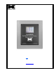
1600/6400-N4X-RD 1.0 Description The Detcon Model 1600-N4X-RD and the 6400-N4X-RD are remote displays for the host Model 1600 and 6400 Control Systems respectively. The 1600-RD is configurable for up to 16 channels and the 6400-RD is configurable for up to 64 channels. They are read only display devices, which show the visual status of the Model 1600 and 6400 Controllers (respectively). The status of gas inputs are displayed on a backlit graphic LCD display that uses a touch-screen user interface.
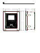
1600/6400-N4X-RD 3.0 Installation Securely mount the Model 1600/6400-RD enclosure. 11.85" 6.78" 6.47" R 9.0" 13.2" Model 6400-N4X-RD 13.73" R Gas Detection Control System Remote Display Mounting feet Figure 1 Dimensional Connect 110/220VAC input wiring to the terminals labeled “VAC (L1)”, “Neutral (L2)”, and “Ground” (See Figure 2). For 220Volt Units connect L1 to the terminal labeled “VAC (L1)”, L2 to the terminal labeled “Neutral (L2)” and Ground to the terminal labeled “Ground”.
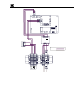
1600/6400-N4X-RD Red 18AWG Black 18AWG J4 J3 Serial Communications PCB +- VDC IN S B A White 22AWG Purple 22AWG A RS-485 Input Output B S J3 J7 RS-232 I/O S1 6400 Controller PCB No Comm Fault Relay PCB RV1 8 7 6 5 4 3 2 1 S2 C NO NC Remote Alarm Reset PCB 1 2 J1 Black 18AWG Red 18AWG 1 2 3 + + J1 4 5 6 Supply 24VDC Power NFS40-7624 L1 1 P1 Gnd Black 18AWG Legend: Pre-Wired Customer Wired 6 7 4 5 1 2 3 8 Gray 18AWG Gray 18AWG Remote Alarm Reset Switch Green 16AWG White
1600/6400-N4X-RD 5.0 Operator Interface 5.1 Using the Touch-screen Display The Operator Interface is conducted through a graphic touch-screen backlit display. A suitable small blunt device such as the Detcon stylus wand should be used to conduct touch-screen interaction. NOTE: Sharp objects such as pens, pencils, screwdrivers…. etc. will permanently damage the display and void the warranty.
1600/6400-N4X-RD The controller may be configured to have less than eight channels per ‘Zone’. Only those ‘Zones’ with active channels will be displayed. When any channel in a ‘Zone’ has an alarm or fault condition, the ‘Zone’ key will begin to flash, and the controller will automatically display the channels in that ‘Zone”. When there are alarms or faults in multiple ‘Zones’, the controller will display each zone for 10 seconds and rotate to the next ‘Zone’.
1600/6400-N4X-RD Figure 5 Set # Active Channels and Relays Use the up and down arrows to make selections. Press ‘ENTER’ after the appropriate selections for # active gas channels and relay outputs have been made. The number of alarm relays should not be set in the Remote Display, as they have no function. 5.3.2 Modbus™ Addressing of Sensor Inputs Addressing Gas Channels with DA-4 Modules This function is used to identify the “device” and “address” of gas sensor inputs using the DA-4 Module.
1600/6400-N4X-RD Addressing Model 10 and Model 12 Control Cards This function is used to identify the “device” and “address” of Model 10 and 12 control card inputs. Each gas channel will need to have the Channel #, Device, Zone and Address set and must match the configuration entered in the 1600/6400 Controller. Addressing and Setup of Relay Outputs Relay outputs are not utilized on the Remote Display, and should not be set up. 5.3.
1600/6400-N4X-RD 5.3.5 View Alarm History View Alarm History shows the logged incident history of each gas channel. Select the gas channel of interest using the up and down arrows for Channel. The history log will show all recorded events including alarms, faults and maintenance records. These are displayed from most recent to last. They are displayed in blocks of eight entries. Entries will show the date/time and the specific condition of when the incident was started.
1600/6400-N4X-RD 5.3.7 Edit Date and Time Edit Date and Time is used to set the current date and time. This should be checked periodically to verify that the time is correct. Reset the time as necessary. Use the up and down arrows enter the correct date and time and press ‘ENTER’ when complete. Figure 11 Set Time and Date 5.3.8 4-20mA Output Setup 4-20mA outputs are not utilized on the Remote Display, and should not be set up. 5.3.
1600/6400-N4X-RD the screen contrast using the up and down arrows. When the screen contrast is satisfactory, press the ‘ENTER’ key to save the settings. Figure 13 Screen Utilities To adjust the calibration of the touch screen key alignment, press the ‘TOUCH SCREEN’ key. The controller will take the user through a series of prompts to execute calibration. Touch the center of each target for best results. When calibration is complete press the ‘OK’ key and then press the ‘ENTER’ key to save the settings.
1600/6400-N4X-RD Figure 14 Non-Protected vs. protected Figure 15 Dip-switches 7.0 Spare Parts 360-612400-024 500-003052-200 500-003052-500 40 Watt 24VDC power supply 1600 Remote Display Controller with LCD 6400 Remote Display Controller with LCD 8.
00/6400-N4X-RD Power Consumption 20 Watts Display 5 inch diagonal Graphic Backlit LCD with Touch Screen Electrical Classification NEMA 4 Dimensions 11.75''W x 13.75''H x 6.75''D Operating Temperature Range -20°C to +55°C Warranty Two years 9.0 Warranty Detcon, Inc., as manufacturer, warrants under intended normal use each new Model 1600/6400-N4X-RD to be free from defects in material and workmanship for a period of two years from the date of shipment to the original purchaser.
1600/6400-N4X-RD 13.75" 12.7" Model 6400-N4X-RD Gas Detection Control System Remote Display ALARM RESET Remote Alarm Reset Mounting Brackets 9" 11.85" 6.75" 6.45" Figure 16 Dimensional Overview 1600/6400-N4X-RD- Instruction Manual Rev. 1.
Rev. 1.
1600/6400-N4X-RD Red 18AWG Black 18AWG J4 J3 Serial Communications PCB +- VDC IN S B A White 22AWG Purple 22AWG A RS-485 Output B Input S J3 J7 RS-232 I/O S1 6400 Controller PCB No Comm Fault Relay PCB RV1 8 7 6 5 4 3 2 1 S2 C NO NC Remote Alarm Reset PCB 1 2 J1 Black 18AWG Red 18AWG 1 2 3 + + J1 4 5 6 Supply 24VDC Power NFS40-7624 L1 1 P1 Gnd Black 18AWG Legend: Pre-Wired Customer Wired 6 7 4 5 1 2 3 8 Gray 18AWG Gray 18AWG Remote Alarm Reset Switch Green 16AWG White
1600/6400-N4X-RD Red 18AWG Black 18AWG J4 J3 +- VDC IN S B A White 22AWG Purple 22AWG A RS-485 Input Output B S J3 J7 Serial Communications PCB 6400 Controller PCB No Comm Fault Relay PCB S1 C NO NC RV1 S2 87654321 Black 18AWG Red 18AWG NC COM 1 2 3 4 + + J1 5 Z-Purge Pressure Switch Supply 24VDC Power NFS40-7624 L1 1 Black 18AWG P1 Gnd J1 1 2 Black 18AWG BYPASS Enclosure Bypass Switch 6 7 4 5 1 2 3 8 Gray 18AWG Gray 18AWG Remote Alarm Reset Switch Green 16AWG White 18