detcon inc. Detcon Model 110A-FB Gas Detection System Operator's Instruction Manual May 21, 2002, Document #2473, Rev. 1.1 Table of Contents 1.0 1.1 1.2 1.3 1.4 1.5 1.6 1.7 1.8 1.9 1.10 1.11 1.12 1.13 1.14 1.15 1.16 1.17 1.18 1.19 1.
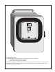
SPECIFIC GAS MONITOR ppm / % MODEL 110A-FB HIGH LOW FAULT H O U S T O N HIGH ALARM NL HIGH ALARM SET detcon inc. T E X LOW ALARM SET A S LOW ALARM NL 1.0 INTRODUCTION The Detcon Model 110A-FB gas detection system consists of 2 major assemblies: 1. The NEMA 4 fiberglass control enclosure. 2. The remote mount gas sensor assemblies. The NEMA 4 fiberglass control enclosure is detailed in section 1.0 of the manual and any applicable sensor assemblies are detailed in section 3.0.
1.1 DESCRIPTION Detcon Model 110A-FB is a single channel gas detection system, designed to supervise and display the status of remote sensor assemblies that monitor ambient air for a variety of toxic and combustible gases. The digital controls are compatible with a linear 4-20 madc input signal. The front panel features a direct reading 2 digit display of the concentration of gas and 3 alarm functions that are status displayed via light emitting diodes.
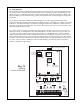
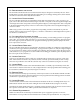
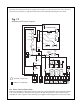
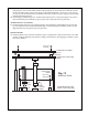
1.2 PROGRAMMING THE 110A-FB The 110A-FB controller board has several functions that may be changed or activated by the user. These include alarm set points, alarm firing direction (descending or ascending), latching alarms, alarm disable and other functions that will be fully discussed below. 1.3 ALARM LEVEL PROGRAMMING The Low and High alarm levels are adjustable in single digit increments from 1 to 99% of scale. To program, refer to SW1, SW2, SW3 and SW4 (see figure #1).
slow blow fuse mounted on the power supply protects against excessive line power (117 VAC). Excessive DC current is protected by a 1 amp micro-fuse located on the motherboard (see figures #1 and #2). Fig.
modules consists of “+” and “–” power loop and the 4-20 madc signal loop referenced to the “–” power loop. The fault relay is normally energized and will de-energize in the event of open power or signal loop between sensor and control module. Additionally, the fault circuit will illuminate the front panel fault LED.
03. If applicable, connect the 24 VDC standby battery to the lugless terminal strip (labeled VDC IN) on the controller motherboard (see figure #4). The DC current load is a maximum 1 amp. Caution: Observe correct polarity when terminating all input/output field wiring. Failure to do so may result in circuit damage on power up. 04. If applicable, connect a normally open momentary remote mounted switch to the lugless terminal strip (labeled RESET) located on the controller motherboard (see figure #4). 05.
Refer to section 3.0 for additional sensor start-up detail. 1.14 SPECIFICATIONS Range: 0-99 ppm/% (see section 3.0 for specific gas range) Accuracy/Reproducibility: ± 1% F.S. Operating Temperature: –40° F to +175° F Input Power: 117 VAC/ 24 VDC Power Consumption: max 6 watts Warranty: one year Outputs: 4-20 madc 1.
Part # 954-230050-050 954-540050-020 954-430050-099 954-EQ0050-099 954-ER0050-099 954-EF0050-099 954-EL0050-099 Model # SiH4-110FB SO2-110FB C4H8S-110FB C4H4S-110FB C6H5CH3-110FB C4H6O2-110FB C2H3CL-110FB Range 0-50 PPM 0-20 PPM 0-99 PPM 0-99 PPM 0-99 PPM 0-99 PPM 0-99 PPM Gas Type Silane Sulfur Dioxide Tetrahydrothiophene Thiophane Toluene Vinyl Acetate Vinyl Chloride 1.16 WARRANTY Detcon, Inc.
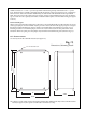
front plate, the control circuit and the ribbon cable (see figure #5). Turn the power switch back on and measure the VDC output on the power supply on the terminals labeled "+ OUT" and "– OUT" (see figure #6). If you do not measure between 22 VDC and 28 VDC, replace the power supply as shown in the breakaway drawing figure #5. 05. If operating by auxiliary DC power, verify that the AUX DC fuse is not open (see figure #1) by removing it and measuring for continuity.
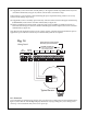
1/2 Amp Slow Blow Fuse PN0297 + OUT 24 VDC Output Terminals – OUT Fig. #6 Power Supply 110A-FB Power Supply PN3506 AUX DC Fuse 1 AMP PN0292 Micro Fuses Sensor FLT LOW HIGH Power 5 AMP 5 AMP 5 AMP 1/2 AMP PN0295 PN0295 PN0295 PN0290 L1 L2 117 VAC IN AUX 24 VDC IN RESET MA C NO NC C NO NC C NO NC SENSOR FAULT LOW HIGH 4-20 OUT 1.19 PARTS LIST VEND # DESCRIPTION QTY RQD ORIG. MFG ORIG.
1.20 RECOMMENDED SPARE PARTS FOR 1 YEAR VEND # DESCRIPTION QTY RQD ORIG. MFG ORIG. MFG # STD QTY LEAD 0290 0292 0295 0297 1/2 amp micro fuse 1 amp micro fuse 5 amp micro fuse 1 amp 3AG slow blow fuse 5 5 5 5 Little Fuse Little Fuse Little Fuse Little Fuse 273.500 273001 273005 313001 5 5 5 5 3 weeks 3 weeks 3 weeks 3 weeks Shipping Address: 3200 A-1 Research Forest Dr., The Woodlands, Texas 7381 Mailing Address: P.O.
Detcon Model 110A-FB Gas Detection System PG.