
Manual
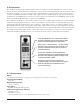


To enter the Program Menu press and hold the front panel switch for 10 seconds until the display reads Pr then release.
M
omentarily pressing the switch again after this will scroll through the program options.
The options are as follows:
Pr Program status
rA Range adjust
A1 Alarm 1 adjust
A2 Alarm 2 adjust
Id RS-485 ID adjust
CA Calibration
tE Test mode
To enter into a function momentarily press the switch until the desired option is shown on the display, then press and
hold the switch for 2 seconds until the display reflects that function’s value. That function’s value can now be adjusted
by momentarily pressing the switch until the desired value is reached. To accept the new value simply hold down the
switch for 2 seconds until the display returns to the Program Menu. The controller will return to normal operation when
there is no key press after 15 seconds.
For example, the following steps would allow adjustment of alarm 1:
1. During normal operation press and hold the switch for 10 seconds until the display reads
Pr.
2. Momentarily press the switch and the display will read
rA.
3. Momentarily press the switch and the display will read
A1.
4.
Pr
ess and hold the switch for 2 seconds until t
he display shows the alarm 1 set-point, i.e.
30.
5. Now momentarily press the switch to change the alarm set-point to the desired value.
6. Press and hold the switch to accept the new value. The display will return to displaying
A1.
The controller will return to normal operation when there is no key press after 15 seconds.
2
2
.
.
4
4
.
.
2
2
P
P
r
r
o
o
g
g
r
r
a
a
m
m
S
S
t
t
a
a
t
t
u
u
s
s
.
.
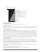
The Program status function (Pr) scrolls through and displays the controllers current settings. Upon entering this func-
tion the display will read somewhat as follows depending on the settings.
rA/99 Range is set to 99
A1/20 Alarm 1 is set at 20
A2/40 Alar
m 2 is set to 40
Id/01 Modbus ID is set to 01
2
2
.
.
4
4
.
.
3
3
R
R
a
a
n
n
g
g
e
e
A
A
d
d
j
j
u
u
s
s
t
t
m
m
e
e
n
n
t
t
The r
ang
e function (
rA) allo
w
s t
he adjus
tment of t
he full scale r
eading of t
he controller. Range is adjustable between 5 and
99 on a two digit controller and between 5 and 999 on a three digit controller. Range is adjustable in 5ppm/% increments.
2
2
.
.
4
4
.
.
4
4
A
A
l
l
a
a
r
r
m
m
1
1
a
a
n
n
d
d
A
A
l
l
a
a
r
r
m
m
2
2
A
A
d
d
j
j
u
u
s
s
t
t
m
m
e
e
n
n
t
t
The Alarm adjustment functions (A1 & A2)allow for the adjustment of the alarm trip point levels in 1ppm/% incre-
ments. Alar
ms ar
e adjus
t
able be
tween 10% and 90% of the Range of the controller. Example: If the range is set to 99,
t
he alar
ms can be adjus
t
ed between 10 and 90. During adjustment the appropriate LED for that alarm will light.
2
2
.
.
4
4
.
.
5
5
M
M
o
o
d
d
b
b
u
u
s
s
I
I
D
D
A
A
d
d
j
j
u
u
s
s
t
t
m
m
e
e
n
n
t
t
The Modbus ID adjus
tment function (
Id) allo
ws for the setting of the Modbus address for serial communications. The
addr
ess is adjus
t
able and displayed in Hexadecimal format between 01 and FF.
2
2
.
.
4
4
.
.
6
6
C
C
a
a
l
l
i
i
b
b
r
r
a
a
t
t
i
i
o
o
n
n
M
M
o
o
d
d
e
e
This function (CA) puts the controller in a mode in which it will behave normally except that it will ignore all alarms and
output a 2mA signal until it is t
aken out of this mode. When in this mode the fault LED will flash and the fault relay will
actuate. To return to normal mode enter the program menu by holding for 10 seconds and then select the CA function
again and hold for 2 seconds.
Model 10 Single Channel Digital Control Module PG.7