
Manual


is to have the fault relay normally energized so that in the event of a power failure to the control module card, the fault
relay will de-energize causing its relay contacts to change state, thereby creating a fault output.
It must be noted that when an alarm relay is jumper programmed as normally energized, the contact outputs, normally
open and normally closed, become reversed. The normally open contact becomes the normally closed and vice versa.
Reconfiguration of the contact output jumpers may be required.
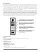
To program an alarm for normally energized operation, slide its corresponding switch to the “on” position. For normal-
ly de-energized operation slide the switch to the “off” position. The switch locations are as follows: fault – SW2-1, alarm
1 - SW2-7, and alarm 2 – SW2-4.
2
2
.
.
3
3
.
.
3
3
A
A
s
s
c
c
e
e
n
n
d
d
i
i
n
n
g
g
o
o
r
r
D
D
e
e
s
s
c
c
e
e
n
n
d
d
i
i
n
n
g
g
A
A
l
l
a
a
r
r
m
m
s
s
Alarm 1 and alarm 2 can be switch programmed to operate during ascending or descending gas conditions. This feature
is useful mainly for the monitoring of oxygen deficiency whereas a decrease in oxygen concentration poses a danger to
personnel. However, there may be other applications where the monitoring of a specific gas concentration is desired and
alarms can be programmed to operate when that concentration exceeds or drops below a predetermined range. Typically,
mos
t applications of monitoring for toxic or combustible gases will warrant that the alarm be programmed as ascending.
To program an alarm for ascending gas conditions, slide its corresponding switch to the “on” position. For descending gas
conditions slide t
he switch to the “off” position. The switch locations are as follows: alarm 1 - SW2-6, and alarm 2 – SW2-3.
2
2
.
.
3
3
.
.
4
4
D
D
i
i
s
s
p
p
l
l
a
a
y
y
C
C
o
o
n
n
f
f
i
i
g
g
u
u
r
r
a
a
t
t
i
i
o
o
n
n
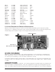
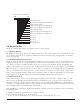
The controller uses standard seven-segment displays and comes from the factory pre-configured for a particular range of
detection. The two digit version is standard. A three digit version is also available and is standard for oxygen. A switch is
used to pr
og
ram the controller for 2 or 3 digit operation. Additional switches are used to turn on the individual deci-
mal places on the displays. These features are preconfigured at the factory and should not require further adjustment.
SW3-1 selects between a 2 digit or 3 digit display. SW3-3 will turn the decimal point either on or off, and SW3-2 sets
the location of the decimal point.
2
2
.
.
3
3
.
.
5
5
D
D
e
e
t
t
e
e
c
c
t
t
o
o
r
r
P
P
o
o
w
w
e
e
r
r
S
S
e
e
n
n
s
s
e
e
S
S
w
w
i
i
t
t
c
c
h
h
This switch should be lef
t in the “ON” position at all times.
2
2
.
.
3
3
.
.
6
6
A
A
l
l
a
a
r
r
m
m
2
2
S
S
i
i
l
l
e
e
n
n
c
c
e
e
Alar
m 2 can be switch programmed to allow it to be reset in the event of an alarm, even if the alarm condition still
exists. This feature would be mainly used if there were a strobe light activated by Alarm 1 and a horn Activated by
Alarm 2. In the event of an alarm both the horn and strobe would be engaged but the horn could be silenced and
would remain silenced until the alarm condition went away and a new alarm occurred. To program Alarm 2 for the
silence f
eatur
e tur
n t
he switch “on”. For normal operation of Alarm 2 turn the switch off. This switch is located at
SW3-5.
2
2
.
.
3
3
.
.
7
7
A
A
l
l
a
a
r
r
m
m
R
R
e
e
s
s
e
e
t
t
An alarm reset switch (SW1), located on the control module face plate is used to reset alarms that have been pro-
grammed as latching. Once alarm conditions have cleared, alarms may be reset by simply pushing the momentary
switch and releasing it.
R
emo
t
e r
eset outputs are also a feature of the Model 10 control module. This feature is available when used in conjunc-
tion wit
h Model 1
0 com
patible control enclosures and mainframe motherboards.
2.4 CONTROLLER OPERATION AND MENU SELECTIONS
Upon applying power, the display will show dC for approximately 2 seconds. The controller will then enter normal oper-
ation mode, displa
ying the gas concentration. There is a 15 second period after power-up in which alarms are ignored.
2
2
.
.
4
4
.
.
1
1
S
S
e
e
l
l
e
e
c
c
t
t
i
i
n
n
g
g
a
a
n
n
d
d
A
A
d
d
j
j
u
u
s
s
t
t
i
i
n
n
g
g
M
M
e
e
n
n
u
u
S
S
e
e
l
l
e
e
c
c
t
t
i
i
o
o
n
n
s
s
Besides acting as an alarm reset, the front panel switch is used to access and navigate through the programming menu
system. The Switch functions as both an Enter Key, and as a Selection Key. When it is pressed and held for more than 2
seconds it will act as an Ent
er K
e
y
. When it is moment
arily pressed it acts as a Select Key.
Model 10 Single Channel Digital Control Module PG.6