
Manual


HBr-10 0-30 PPM Hydrogen Bromide HBr
HCL-10 0-30 PPM Hydrogen Chloride HCL
HCN-10 0-30 PPM Hydrogen Cyanide HCN
HF-10 0-10 PPM Hydrogen Fluoride HF
CH30H-10 0-100 PPM Methanol CH30H
CH3SH-10 0-100 PPM Methyl Mercaptan CH3SH
NO-10 0-100 PPM Nitric Oxide NO
NO2-10 0-5 PPM Nitrogen Dioxide NO2
O3-10 0-1 PPM Ozone O3
COCL2-10 0-1 PPM Phosgene COCL2
PH3-10 0-5 PPM Phosphine PH3
SiH4-10 0-50 PPM Silane SiH4
SO2-10 0-20 PPM Sulfur Dioxide SO2
C4H8S-10 0-100 PPM Tetrahydrothiophene C4H8S
C4H4S-10 0-100 PPM Thiophane C4H4S
C4H6O2-10 0-100 PPM Vinyl Acetate C4H6O2
C2H3CL
-10 0-100 PPM Vinyl Chloride C2H3CL
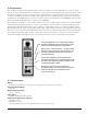
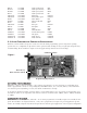
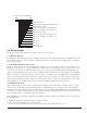
2.3 ALARM FUNCTIONS AND CONTROLLER CONFIGURATION
Model 1
0 control modules incorporate several user selectable alarm programming options and general operating
options that are accomplished via dip switches. These options include latching of relays, energized/de-energized relays,
and alarm firing direction. Reference Figure #1 for the applicable dip switch locations and settings.
2
2
.
.
3
3
.
.
1
1
L
L
a
a
t
t
c
c
h
h
i
i
n
n
g
g
o
o
r
r
n
n
o
o
n
n
-
-
L
L
a
a
t
t
c
c
h
h
i
i
n
n
g
g
R
R
e
e
l
l
a
a
y
y
s
s
All alar
ms — alar
m 1
, alar
m 2, and f
ault — can be jum
per pr
ogrammed to operate as latching or non-latching. If an
alar
m is pr
og
rammed to latch, its corresponding relay and LED indicator, once activated, will stay activated until the
reset button is pressed (assuming, of course, that alarm conditions have cleared).
T
o pr
og
ram an alarm for latching operation, slide its corresponding switch to the on position. For non-latching opera-
tion slide the switch to the off position. The switch locations are as follows: fault – SW2-2, alarm 1 - SW2-8, and alarm
2 – SW2-5.
2
2
.
.
3
3
.
.
2
2
E
E
n
n
e
e
r
r
g
g
i
i
z
z
e
e
d
d
o
o
r
r
D
D
e
e
-
-
e
e
n
n
e
e
r
r
g
g
i
i
z
z
e
e
d
d
All alarms relays — alarm 1, alarm 2, and fault — can be switch programmed as normally energized or normally de-ener-
gized. The standar
d is de-ener
gized. However, a relay can be programmed as energized to provide application specific
features. A normally energized relay will de-energize when in alarm. A typical application of the energized configuration
Model 10 Single Channel Digital Control Module PG.5
Alarm Reset/
Menu Interface Switch
Programming Dip Switches
Calibration Switch
SW2 SW3
Figure 1