
Manual


4. Alarm 1 is set to 20% of the default range.
5. Alarm 2 is set to 50% of the default range.
6. The RS-485 address is set to 01h.
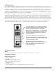
2.10 CONTROLLER CALIBRATION
The 4-20 mA output of the Model 10 control module is calibrated at the factory and should require no further adjust-
ment. If under some special circumstance calibration is required, use the following instructions. To calibrate the controller
you will need an extender card and have to be able to simulate a 4mA input and a 20mA input.
2
2
.
.
1
1
0
0
.
.
1
1
C
C
a
a
l
l
i
i
b
b
r
r
a
a
t
t
i
i
n
n
g
g
Z
Z
e
e
r
r
o
o
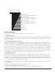
Follow the steps below to calibrate the zero (4 mA) signal level input:
1. Input a 4ma signal to the controller.
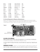
2. Press and hold the calibration switch SW4 (see figure 1) until the display reads
CL. After 3 seconds the display will
read
2E (zero).
3. Press and hold SW4 until the display flashes
2E. The zero reading has been read and saved. The output 4-20 mA
should now reflect the input signal. The display will stop flashing and display
2C (zero complete) for 3 seconds and
will r
eturn to displaying
2E. The contr
oller will return to normal operation if there is no key press after 15 seconds
or by pressing the front panel switch.
2
2
.
.
1
1
0
0
.
.
2
2
C
C
a
a
l
l
i
i
b
b
r
r
a
a
t
t
i
i
n
n
g
g
S
S
p
p
a
a
n
n
Follow the steps below to calibrate the span (20 mA) signal level input.
1. Input a 20 mA signal to the controller.
2. Press and hold the calibration switch SW4 (see figure 1) until the display reads CL. After 3 seconds the display will
read
2E (zero).
3. Momentarily press SW4 until the display reads
SP.
4. Press and hold SW4 until the display flashes
SP. The span reading has been read and saved. The output 4-20 mA
should now r
ef
lect the in
put signal. The display will stop flashing and display
SC (span comple
te) for 3 seconds and
will return to displaying
SP. The controller will return to normal operation if there is no key press after 15 seconds
or by pressing the front panel switch.
2.11 WARRANT
Y AND
SER
VICE
POLICY
Detcon, Inc., as manufacturer, warrants each new Model 10 series digital electronic control module to be free from
defects in material and workmanship under intended normal use for a period of one year from date of shipment to the
original purchaser. Detcon, Inc., additionally provides for a fixed fee repair/replace service policy which covers Model
1
0 ser
ies digit
al contr
ol modules for a per
iod of f
iv
e y
ears. The fixed fee service policy shall affect any necessary factory
repair for the period following the one-year warranty period and shall end five years after expiration of the warranty.
The f
ixed policy rate is $75.00 per control module, per transaction, during the period of the policy. The policy is FOB
De
tcon, Inc., The W
oodlands, T
exas.
Model 10 Single Channel Digital Control Module PG.10
Shipping Address: 3200 A-1 Research Forest Dr., The Woodlands, Texas 7381
Mailing Address: P.O. Box 8067, The Woodlands, Texas 77387-8067
phone 888-367-4286, 713-559-9200 • fax 281-292-2860 • www.detcon.com • sales@detcon.com