Instructions 95-8400-01 PathWatch™ Open Path IR Beam Detector PW9200A1 Series Detector Electronics Corporation 6901 West 110th Street • Minneapolis, Minnesota 55438 USA Tel: 952.941.5665 or 800.765.3473 • Fax: 952.829.
Table of Contents Section I- General Information Section III - Maintenance General Description ..........................................1 General Precautions ........................................16 Features ............................................................1 General Information .........................................16 Specifications ....................................................2 Access to Internal Components ......................16 Functional Description ....................
DET-TRONICS ® INSTRUCTIONS PathWatch™ Open Path IR Beam Detector PW9200A1 Series Section 1 General Information The installation, operation and maintenance instructions contained in this manual are for use by qualified personnel only. All personnel assigned to this equipment should read the instructions provided before initiating any procedures. The manual should be maintained on file so that it is available to installation, operation and maintenance personnel.
SPECIFICATIONS HYDROCARBON VAPOR ALARM OUTPUT— SPST relay, rated at 7 amperes continuous, 120 vac/240 vac or 28 vdc. Also rated at 1/3 HP at 120 vac, 1/2 HP at 240 vac. Contacts are closed under normal clean air conditions and open when vapors are detected. HOUSING SIZE— Transmitter and receiver dimensions are identical: 12-1/4 inches (W) x 11-1/2 inches (H) x 9-1/2 inches (D).
Filterwheel Motor Amplifiers This motor is a small 115 vac shaded pole ball bearing motor. The filterwheel is attached to the motor shaft. The signal at the photodetector is amplified by the preamplifier circuitry. The gain of the preamplifier can be adjusted with a potentiometer to optimize the signal strength for long or short operating distances. Filterwheel The amplified signal is fed to the AGC amplifier, which maintains the signal within the proper operating range.
The light beam projected by the PW9200 transmitter could cause combustible materials within its path to ignite or raise the temperature of an object within its path above the self-ignition temperature of some gases. Check the temperature code for the transmitter wattage used (see instrument nameplate) and do not install the instrument at any location where this dangerous condition could occur.
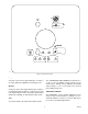
ZERO SPARE FUSE 1A OUTPUT TEST ALIGN OPERATE MODE CALIBRATION ADJUSTMENT FUSE 1 A O LO MID V mA HI SIG GND OUTPUT SELECT OUTPUT RATIO DENOM SENSITIVITY OUT OPT VAPOR ALARM NUM SETPOINT ADJUST A1395 Figure 2—Front Panel Controls Align CALIBRATION ADJUSTMENT POTENTIOMETER A shorter response time (approximately 2 seconds) is used only during the alignment and testing process. The CALIBRATION ADJUSTMENT potentiometer is used to scale the RATIO output voltage for the desired span.
Hi OUT OPT (violet) This position sets the instrument for the highest sensitivity available. PW9200 instruments are factory set and calibrated at HI sensitivity. The OUT OPT test jack permits access to the optional RATIO output (used only with the options P.C. board). FUSE Mid The power line fuse has been located on the front panel for accessibility. This position decreases the sensitivity of the instrument by a factor of 3.
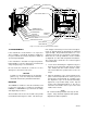
DC POWER SUPPLIES OPTICAL FILTER IR LENS IR WINDOW OPTIONS PC BOARD FILTERWHEEL AGC/TE COOLER PC BOARD THERMOELECTRICALLY COOLED PHOTODETECTOR FILTERWHEEL MOTOR SYNC PICKOFF REAR PANEL PC BOARD STATUS RELAY PREAMPLIFIER PC BOARD REAR PANEL PC BOARD DUAL RATIO PC BOARD PREAMP GAIN CONTROL CONNECTOR/RELAY PC BOARD SIGNAL CONNECTOR A1396 POWER CONNECTOR Figure 3—Location of Receiver Boards and Assemblies mits height, horizontal pan and vertical tilt adjustments to optically align the instrument for m
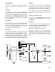
ALIGNMENT TARGET PROTECTIVE CAPS (2) ALIGNMENT SCOPE CROSSHAIR ADJUSTMENTS (2) SCOPE LAMP SCREWS (2) 4 3/8" SCOPE RECEIVER BRACKET LOCKING KNOB ASSEMBLY PAN ADJUSTMENT KNOB ASSEMBLY FOOT BASE 12" U-BOLTS (2) TILT ADJUSTMENT KNOB ASSEMBLY FOOT BASE 14" USER-SUPPLIED MOUNTING PIPE, 4 1/2 O.D. 14 1/4" A1397 FRONT VIEW SIDE VIEW Figure 4—Pan Tilt Mount USER SUPPLIED POST 4.6 MAX O.D. 3.5 MIN O.D. JUNCTION BOX ALL ELECTRICAL CONNECTIONS ARE MADE WITHIN THIS BOX. 18 MAX.
with the instrument, as shown in Figure 5. Be sure to attach the receiver to the mount marked “R” and to attach the transmitter to the mount marked “T”, and to match the serial number of the instrument with the serial number of the mount. The mounting surface should be vertical with the transmitter and receiver roughly facing each other.
1. Adjust the locking knob assembly on the back plate of each mount so that the end of the shaft is at least 1-1/2 inch from the front plate. (See Figure 4 for illustration of the pan-tilt mount.) WARNING If both conduit entrances to the junction box are not used, the unused entrance must be fitted with an explosion-proof pipe plug with at least five full threads engaged. 2.
the reflection is visible in the receiver window when standing at the transmitter. er P.C. board within the heat sink fins. The preamplifier gain adjustment potentiometer is located on the preamplifier P.C. board and can be reached by inserting a screwdriver between the fins from the bottom of the heat sink (as viewed when the housing cover is open, but attached to the housing by its hinges). 8. Remove the window assembly and check the signal at the NUMERATOR test jack (blue) on the digital voltmeter.
ALIGNMENT HEAVY HYDROCARBON RESPONSE CONFIDENCE TEST View the transmitter through the receiver alignment scope to verify that the cross hairs of the scope are centered on the target attached to the transmitter mount. If the cross hairs are not centered on the target, alignment has changed. Adjust the pan and/or tilt of the receiver until the cross hairs of the alignment scope are centered on the target.
ohms. The 4 to 20 ma output is surge protected. determine the average ppm concentration in the operational path length. The RATIO output in this manual is indicated in 0 to 10 vdc. For instruments using the 4 to 20 ma output, the standard 0 to 10 vdc output can be read at the RATIO test jack (brown) on the front panel or at the receiver junction box when the OUTPUT SELECT switch is set to the V position. In addition, a voltage to current transfer curve is provided. See Figure A2.
1. Attach the Flowmeter Outlet Hose to the appropriate hose fitting on the Calibration Tube as shown in Figure 8. 8. Attach the calibration gas cylinder to the flowmeter inlet hose, making sure that the regulator is shut. At the junction box, attach a digital voltmeter with a resolution of at least 1 millivolt dc between the RATIO output (terminal 1) and SIGNAL GROUND (terminal 2). 2. Remove the two protective caps from the Calibration Tube.
B. The hydrocarbon vapor cloud is smaller than the path length. HYDROCARBON VAPOR ALARM THRESHOLD ADJUSTMENT In critical applications, it is recommended that the calibration be checked before setting the alarm threshold. Based on the specific application of the instrument, select the concentration in ppm at which the Hydrocarbon Vapor Alarm will activate. It is important to remember that the open path detector measures the average gas concentration over a continuous series of points along a path.
RECEIVER FUNCTION Section 3 Maintenance Infrared Photodetector Detector/Preamp assembly Sync Circuitry Rear panel p.c. board and sync demod p.c. board Amplifier Preamp p.c. board and sync demod p.c. board Signal Processing Electronics AGC/TE cooler and sync demod p.c. board Ratiometer Rear panel p.c. board Threshold Detector Rear panel p.c. board OR Gate Function Connector/relay p.c. board Obstruction/Status Alarm Relay Connector/Relay p.c. board Adjustable Threshold Detector Rear panel p.c.
4. Disconnect the connector plug(s) from the receptacle(s). The transmitter has one connector and the receiver has two connectors. The instrument can be inspected or serviced on-site while the cover is opened and attached by its hinges. If service is to be performed off-site, the cover and attached components can be removed from the housing as described in Step 5. board, make sure that the notch on the board matches the key in the connector and slide the board along the card guides into the motorbox.
To remove: SYNC PICKOFF 1. Release the ribbon connector that connects the AGC/TE cooler board to the preamplifier board, which is permanently attached to the bottom of the heat sink. The sync pickoff is mounted in a socket, which is located in the center of the rear panel p.c. board. The sync pickoff is removed by pulling if from the socket. To replace the sync pickoff, install with the red dot up (toward the motorbox connectors). 2.
5. Remove the nut that holds the hub to the filterwheel and detach the filterwheel from the hub. DO NOT TOUCH filters with bare hands. WINDOWS Interior windows are reached by removal of the transmitter and receiver window assemblies. Clean as described in “Exterior optical cleaning” procedure above. 6. Remove the nut from the replacement motor hub and slide the filterwheel onto the replacement motor shaft.
NOTE DO NOT TOUCH the lamp envelope with bare fingers. Use the lamp wrapper provided with the new lamp, clean white gloves, or clean optical tissue when inserting a new lamp. Also, be careful to avoid touching the inner surface of the reflector. SYMPTOM: Transmitter lamp consistently burns out before 6 months. POSSIBLE CAUSE: Constant high line voltage. CHECK: Voltage into transmitter. Should be nameplate voltage rating (±10%). REMEDIAL ACTION: Reduce power line voltage. 7.
POSSIBLE CAUSE: Object in beam. REMEDIAL ACTION: Remove obstruction. SYMPTOM: Voltage at NUMERATOR (blue) test jack relative to GROUND (green) is not within 0.3 to 0.5 vdc after proper alignment and output zero adjustment. SYMPTOM: HC Alarm does not activate when hydrocarbon vapors are present in monitored path, or HC Alarm activates too often. POSSIBLE CAUSE: Improper preamplifier gain setting for path length. REMEDIAL ACTION: See Step 14 of “Optical Alignment/Signal Strength” procedure.
If malfunctions cannot be corrected by carefully following the procedures described in this manual, contact the factory for assistance. In many cases, sufficient information to correct the malfunction can be provided over the telephone. If it is necessary to contact the factory by telephone, it is helpful to have the operation and maintenance manual accessible and to obtain the following readings for the service technician: Pack the unit or component properly.
Appendix line between the mirror and the receiver, keeping the reflection of the transmitter lamp in sight. Once on the direct line, the second person should back away from the mirror toward the receiver, keeping the reflection sighted. The first person should adjust the pan and tilt of the mirror so that the second person keeps the reflection in sight as he gradually backs up to the center of the receiver.
fins from the bottom of the heat sink (as viewed when the cover is open, but attached to housing by its hinges). If the output voltage is less than the specified minimum, turn the preamplifier gain potentiometer clockwise. If the output voltage is greater than 0.5 vdc, turn the preamplifier gain potentiometer counterclockwise. 13.
L 115 VAC – LINE N 115 VAC – NEUTRAL POWER GROUND 1 CHANNEL 1 OUTPUT 2 SIGNAL GROUND 3 CHANNEL 3 OUTPUT 4 STATUS ALARM – COMMON 5 STATUS ALARM – N.C. 6 HC ALARM – N.C.
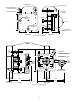
Figure A3 Figure A4 26
Figure A5 Figure A6 27 95-8400
Figure A7 Figure A8 28
Figure A9 Figure A10 29 95-8400