Instructions 95-8493-02 Dual Spectrum® Infrared Flame Detector PM-5MP & PM-5MP+ Detector Electronics Corporation 6901 West 110th Street • Minneapolis, Minnesota 55438 USA Tel: 952.941.5665 or 800.765.3473 • Fax: 952.829.
Table of Contents APPLICATIONS . . . . . . . . . . . . . . . . . . . . . . . . . . . . . . . . . 1 DETECTOR USE IN HAZARDOUS AREAS . . . . . . . . . . . 2 ELECTRICAL CHARACTERISTICS . . . . . . . . . . . . . . . . . . 2 ENVIRONMENTAL CHARACTERISTICS . . . . . . . . . . . . . 3 DETECTOR PERFORMANCE . . . . . . . . . . . . . . . . . . . . . . 3 Detection Range and Response Time . . . . . . . . . . . 3 False Alarm Immunity . . . . . . . . . . . . . . . . . . . . . . . . 4 DETECTOR INSTALLATION . . . . . . . .
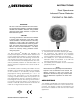
DET-TRONICS INSTRUCTIONS ® Dual Spectrum® Infrared Flame Detector PM-5MP & PM-5MP+ IMPORTANT Be sure to read and understand the entire instruction manual before installing or operating the Model PM-5MP and PM-5MP+ Detectors. Only qualified personnel should install, maintain or operate the flame detection system. CAUTION The wiring procedures in this manual are intended to ensure proper functioning of the device under normal conditions.
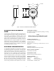
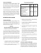
3.1 1.7 4 x 0.102 2.5 3.1 2.5 A2204 Figure 1—Dimensions of PM-5MP and PM-5MP+ Detectors DETECTOR USE IN HAZARDOUS AREAS OPERATING VOLTAGE— 9 to 30 VDC at the detector (observe polarity), including line drops and ripple.
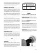
Table 1—PM-5MP and PM-5MP+ Wiring Harness Identification 15° 30° Wire Color Description Black Brown Red Orange Yellow Green Blue Violet Gray White Power Return Power Return V+, Input Power V+, Input Power Alarm + Alarm + Alarm – Alarm – Trouble + Trouble – 45° 55° 0° 100% 15° 90% 80% 30° 70% 60% 50% 45° 55° 40% 30% 20% 10% A2004 Figure 2—Graphical Representation of Detector Range as a Function of Angle from the Optical Axis T0044 VIBRATION— Compliance with FMR Approval Standard 3260.
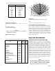
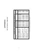
Table 3—False Alarm Immunity Distances (Factory Mutual Research Verified) FALSE ALARM IMMUNITY The PM-5MP and PM-5MP+ are highly resistant to false alarms. However, no flame detector is perfect — a fire alarm output due to non-fire stimuli is possible. Table 3 lists common stimuli and the false alarm immunity distance for those stimuli, as tested by Factory Mutual Research. No false alarms occur for larger distances in laboratory measurements.
(Drawing 420031, Appendix A). Detectors may be wired in a standard NFPA class B, style B configuration or in a class A, style D configuration. Approved initiating device circuits may be either intrinsically safe, nonincendive, or suitable for the classified location as required.
MAINTENANCE 4. Interconnection Wiring. Correct interconnection wiring should be checked by disconnecting any wire from the multi-conductor cable were it is connected to the power or alarm circuit. The result, in an approved wiring scheme, should be a trouble signal indication at the control panel. ROUTINE VISUAL INSPECTION A properly installed PM-5MP detector system is highly resistant to blinding by contamination build-up on the detector front face window.
DEVICE REPAIR AND RETURN ORDERING INFORMATION The PM-5MP and PM-5MP+ are not designed to be repaired in the field. If a problem should develop, carefully check for proper system wiring. If it is determined that the problem is caused by a detector failure, the device must be returned to the factory for repair.
8 CLASS CLASS CLASS CLASS CLASS A, CLASS A, CLASS A, CLASS A, CLASS I, DIV. 2, GROUPS A, B, C & D CLASS II, DIV. 2, GROUPS F & G CLASS III, DIV.
9 95-8493 TROUBLE + STAHL PEPPERL + FUCHS MTL Z978 7278ac MANUFACTURER BARRIER TABLE ALARM – ALARM – ALARM + ALARM + TROUBLE – 9002/77-280-094-00 MODEL PM-5MP+ OR PM-5MP POWER RETURN POWER RETURN V+ V+ HAZARDOUS LOCATIONS: CLASS I, DIV. 1, GP. C, D CLASS II, DIV. 1, GP. E, F, G CLASS III, DIV. 2 28.0 30.0 28.1 Vt (V) 94.0 93.0 87.0 It (MA) BARRIER PARAMETERS ALARM – ALARM + DC RETURN +24 VDC CONTROL ROOM INSTRUMENTATION OPERATING AT OR LESS THAN 250 VOLTS RMS.
10 PM-5MP+ OR PM-5MP PM-5MP+ OR PM-5MP PM-5MP+ OR PM-5MP Hazardous (Classified) Locations: Class I, Division 2, Group A, B, C, D Class II, Division 2, Group F, G Class III, Division 2 Non-hazardous (Non-classified) Locations CLASS B, STYLE B WIRING NONINCENDIVE APPENDIX C Figure C1—Non-Incendive Class B, Style B Wiring (Drawing No.
11 95-8493 NOTES: ALARM – (VIO) TROUBLE + (GRY) TROUBLE – (WHT) PWR RTN (BRN) ALARM + (YEL) ALARM + (GRN) ALARM – (BLU) V+ (ORG) PWR RTN (BLK) V+ (RED) ALARM – (VIO) TROUBLE + (GRY) TROUBLE – (WHT) ALARM – (BLU) PWR RTN (BRN) ALARM + (YEL) ALARM + (GRN) PWR RTN (BLK) V+ (ORG) V+ (RED) TROUBLE + (GRY) TROUBLE – (WHT) ALARM – (BLU) ALARM – (VIO) 5. THE OUTGOING AND RETURN (REDUNDANT) CIRCUIT CONDUCTORS SHALL NOT BE RUN IN THE SAME CABLE ASSEMBLY, ENCLOSURE, OR RACEWAY PER NFPA 72. 4.
12 O N WARNING CHANGE BATTERY IN NON-HAZARDOUS LOCATION ONLY. BATTERY REPLACEMENT THE TEST SET REQUIRES 6 ALKALINE C-SIZE BATTERIES. NOTE FOR VALID TEST RESULTS, THE TEST SET AND THE SENSOR UNDER TEST MUST BE AT APPROXIMATELY THE SAME TEMPERATURE. OPERATION TURN ON PSS-MP, WAIT 15 SECONDS. TO CAUSE AN ALARM, HOLD PSS-MP SO THAT THE INFRARED FILTER LENS IS LESS THAN 1 INCH FROM THE FRONT OF THE FLAME DETECTOR TO BE TESTED. IT CAN TAKE SEVERAL SECONDS FOR THE DETECTOR TO ALARM.
Printed in USA Detector Electronics Corporation 6901 West 110th Street • Minneapolis, Minnesota 55438 USA Tel: 952.941.5665 or 800.765.3473 • Fax: 952.829.