Instructions 95-8676 Infrared Carbon Dioxide Gas Detector PointWatch Eclipse® Model PIRECL 2.
Table of Contents Application . . . . . . . . . . . . . . . . . . . . . . . . . . . . . . 1 Startup . . . . . . . . . . . . . . . . . . . . . . . . . . . . . . . . 18 PIRECL Startup/Commissioning Checklists . . . 18 Operation Overview . . . . . . . . . . . . . . . . . . . . . 1 Theory of Operation . . . . . . . . . . . . . . . . . . . . . . 1 Detectable Gases . . . . . . . . . . . . . . . . . . . . . . . . 2 Outputs . . . . . . . . . . . . . . . . . . . . . . . . . . . . . . . .
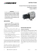
INSTRUCTIONS Infrared Carbon Dioxide Gas Detector PointWatch Eclipse® Model PIRECL Important Be sure to read and understand the entire instruction manual before installing or operating the gas detection system. This product is intended to provide early warning of the presence of carbon dioxide gas. Proper device installation, operation, and maintenance is required to ensure safe and effective operation. If this equipment is used in a manner not specified in this manual, safety protection may be impaired.
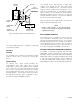
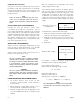
PERMEABLE GAS CELL The onboard tri-color LED indicates a LOW alarm condition via a flashing red color, and a HIGH alarm condition via a steady red color. The Eclipse internal magnetic switch or HART Field Communicator can be used to reset latched alarms. A short-duration magnetic switch activation of 1 second will reset latched alarms. Holding the magnetic switch closed for 2 seconds will start the calibration sequence. The external calibration line will not reset latched alarm relays.
Specifications Warm-up Time (All Models)— Device enters normal mode after two minutes upon cold power-up. One hour warm-up time is recommended for optimum performance. Signal output level during warm‑up is programmable. Input Voltage (All Models)— 24 Vdc nominal. Operating range is 18 to 32 Vdc. Ripple cannot exceed 0.5 volts Peak-to-Peak. Power Consumption (All Models)— Detector without Relays 4.0 watts nominal @ 24 Vdc 7.5 watts peak @ 24 Vdc 10.0 watts peak @ 32 Vdc.
SELF-DIAGNOSTIC TEST— Fail-Safe operation ensured by performing all critical tests once per second. FAULT RELAY— Form C Type (NO/NC). Energized during Normal mode, De-Energized on Fault or loss of power. Contact Rating: 5 amperes at 30 Vdc. Non-Latching Operation only — not programmable. Ingress Protection— IP66/IP67 (DEMKO Verified). DIGITAL OUTPUT (Optional)— Modbus digital communication. Detector Housing Material— 316 stainless steel (CF8M).
Important Safety Notes Certification— ® CAUTION The wiring procedures in this manual are intended to ensure proper functioning of the device under normal conditions. However, because of the many variations in wiring codes and regulations, total compliance to these ordinances cannot be guaranteed. Be certain that all wiring complies with the NEC as well as all local ordinances. If in doubt, consult the authority having jurisdiction before wiring the system.
Installation However, this rule of thumb is subject to change depending upon specific application properties and requirements. NOTE For additional information on determining the quantity and placement of gas detectors in a specific application, refer to the IEC 60079-29-2 standard. Before installing the PointWatch Eclipse detector, define the following application details: Wiring The detector must be installed per local installation practices.
Wire size requirements are dependent upon power supply voltage and wire length. Calibration Gas Port Cover A protective cover for the calibration gas injection port is provided to ensure that contaminants are not accidently introduced into the Eclipse optics. Ensure that this cover is properly installed over the port when calibration is not being performed. The maximum distance between the Eclipse detector and its power supply is determined by the maximum allowable voltage drop for the power wiring loop.
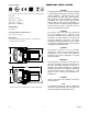
Figure 4 shows the wiring terminal strip located inside the detector’s integral junction box. Figure 5 shows the wiring terminal configuration for the Eclipse CO2 without relays. FACTORY INSTALLED WIRING TO RELAY BOARD (DO NOT REMOVE) Figure 6 shows the wiring terminal configuration for the Eclipse CO2 with relays. CAPTIVE SCREWS (3) Figures 7 through 10 show the 4-20 mA output of the Eclipse detector in various wiring schemes.
EARTH GND LUG A2084 Figure 4—Terminal Strip Located Inside Wiring Compartment 24 VDC – 1 24 VDC + 2 CALIBRATE 3 24 VDC – 4 24 VDC + 5 + 4-20 MA 6 – 4-20 MA 7 RS-485 B 8 RS-485 A 9 RELAY POWER 10 FAULT 11 NO USER CONNECTION LOW ALARM 12 HIGH ALARM 13 WIRING TO OPTIONAL RELAY BOARD NO USER CONNECTION 24 VDC – 1 24 VDC + 2 CALIBRATE 3 24 VDC – 4 24 VDC + 5 + 4-20 MA 6 – 4-20 MA 7 RS-485 B 8 RS-485 A 9 RELAY POWER (RED) 10 FAULT (ORANGE) 11 LOW ALARM (WHITE)
24 VDC 24 VDC – – + 24 VDC – 1 24 VDC – 1 24 VDC + 2 24 VDC + 2 CALIBRATE 3 CALIBRATE 3 24 VDC – 4 24 VDC + 5 24 VDC – 4 24 VDC + 5 * 4 to 20 MA + – + 4-20 MA 6 + 4-20 MA 6 – 4-20 MA 7 – 4-20 MA 7 RS-485 B 8 RS-485 B 8 RS-485 A 9 RS-485 A 9 RELAY POWER 10 RELAY POWER 10 FAULT 11 FAULT 11 LOW ALARM 12 LOW ALARM 12 HIGH ALARM 13 HIGH ALARM 13 NO USER CONNECTION B2050 *TOTAL LOOP RESISTANCE = 250 OHMS MINIMUM, 600 OHMS MAXIMUM.
NO USER CONNECTION 24 VDC – 1 – 24 VDC + 2 + CALIBRATE 3 24 VDC – 4 24 VDC + 5 + 4-20 MA 6 – 4-20 MA 7 RS-485 B 8 RS-485 A 9 RELAY POWER 10 FAULT 11 LOW ALARM 12 HIGH ALARM 13 CALIBRATE SWITCH HOLD CALIBRATION MAGNET AT OUTSIDE BASE OF JUNCTION BOX AT THIS LOCATION TO ACTIVATE CALIBRATION SWITCH 24 VDC 250 TO 500 OHMS B2056 A2203 Figure 12—Remote Calibration Switch and LED in Optional Det-Tronics PIRTB Termination Box Figure 11—Wiring the Eclipse Detector for Benchtop Test
Description If a PIRTB Remote Calibration Termination Box is utilized, the HART Communicator can be connected at the PIRTB. Note that this connection requires removal of the PIRTB cover. Internal Magnetic Switch An internal magnetic switch is provided for resetting latched alarms and initiating calibration. See Figure 14 for switch location. Momentary switch activation will reset alarms, while holding the switch closed for 2 seconds or longer will start the calibration sequence.
Clock Table 1—LED Status Indication LED Device Status Green Normal operation. Red Blinking indicates Low Alarm. On steady indicates High Alarm. Yellow Fault condition or warmup. An hour meter is provided to give a relative indication of time for historical logs. The meter is zeroed at the time of manufacture and only increments while power is applied. HART or MODBUS communication is required to view the running hours.
The following recommendations are provided to enhance operator ease and convenience of remote calibration configurations: Remote Calibration Option In most applications, it is recommended to install the PointWatch Eclipse CO2 model where it will contact the gas of interest as quickly as possible. Unfortunately, the best location for early warning can often result in accessibility problems for the operator when calibration is required.
HAZARDOUS LOCATION NON-HAZARDOUS LOCATION HART COMMUNICATOR PIRECL ISOLATED 4-20 MA PIRTB 24 VDC, CAL 24 VDC + 24 VDC – + 4-20 MA – 4-20 MA CAL GAS HART COMMUNICATOR PIRECL NON-ISOLATED 4-20 MA PIRTB 24 VDC + 24 VDC – 4-20 MA SIGNAL CAL GAS NON-ISOLATED 4-20 MA HART COMMUNICATOR PIRECL PIRTB 24 VDC + 24 VDC – 4-20 MA SIGNAL WRONG HART COMMUNICATOR PIRECL NON-ISOLATED 4-20 MA PIRTB E2060 24 VDC + 24 VDC – 4-20 MA SIGNAL NOTE: THE TOTAL WIRING DISTANCE FROM THE HART COMMUNICATOR THROUGH TH
Operation 4-20 mA Current Loop Output Eclipse provides an isolated, linear current loop output that is proportional to the detected gas level. Fault and calibration status are also indicated by this output. Factory Default Settings The PointWatch Eclipse CO2 model is shipped from the factory pre-calibrated and set for carbon dioxide at 0-2%/vol (0-20000 ppm). The factory setting for full-scale 2%/vol output is 20 mA. HART and MODBUS interfaces also have the ability to calibrate the 4 mA and 20 mA levels.
Fault Indication User Defined Fault Mode There are three modes of signaling faults using the 4-20 mA analog signal output: This mode is intended for users who wish to program unique current levels for faults and calibration signals. User defined current levels can be set from 0.0 to 24.0 mA. and can be programmed from HART or MODBUS interfaces. Four unique current levels are available: warm-up, general fault, calibration, and blocked optics.
Startup Mechanical Checklist When the Eclipse is installed and wired as described in the “Installation” section, it is ready for commissioning. If the application requires that specific changes be made to the configuration settings, HART or MODBUS communication will be required. Refer to the appropriate Appendix for details. note Ensure that controller alarm outputs are inhibited for a minimum of 10 seconds after system power‑up to prevent unwanted output actuation.
Calibration Additional Calibration Notes Calibration Overview important Always ensure that the correct gas type is used for calibration. (2.5 LPM flow rate is recommended.) Although routine calibration of the PointWatch Eclipse is normally not required, the device supports non-intrusive field calibration capability. Two (2) calibration procedure options are provided: note Ensure that the detector has been operating for at least two hours before calibrating. 1.
Calibration Initiation Detailed Calibration Procedure using Magnetic Switch Eclipse calibration may be initiated by any of the following means: • The onboard magnetic calibration switch Refer to Tables 4 and 5 for a quick summary of the standard calibration sequence. • The magnetic calibration switch in the remote termination box 1. Apply Nitrogen gas. • HART communication. 2. Apply magnet for 2 seconds minimum to initiate calibration. A. The onboard LED turns to steady red.
Table 4—Quick Reference Guide for Normal Calibration Procedure Using Magnetic Switch Description Indicating LED (PIRECL/PIRTB) Current Output (default setting) Operator Action Normal-ready to calibrate steady green/off ≥ 4.35 mA* Purge with pure nitrogen if required Initiate Calibration steady red/on-steady 1 mA Apply Nitrogen, apply Magnet for 2 seconds min.
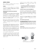
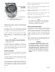
DIFFUSION PATHS INTO MEASUREMENT CHAMBER MIRROR O-RING IR SOURCE LAMP AND WINDOW HYDROPHOBIC FILTER C2059 Figure 17—PointWatch Eclipse with Baffle Removed Maintenance Optics Cleaning Routine Inspection Cleaning of the Eclipse optical surfaces is normally required only if an optical fault is indicated.
Troubleshooting Device Repair and Return A Fault status is indicated by a yellow LED and also by the 4-20 mA output. Refer to Table 6 to identify the fault type using the 4-20 mA output. (The operator must know which fault signaling mode has been programmed.) Refer to Table 7 for assistance in correcting malfunctions with the PointWatch Eclipse Detector. Prior to returning devices, contact the nearest local Detector Electronics office so that a Return Material Identification (RMI) number can be assigned.
Table 7—Troubleshooting Guide Fault Condition Corrective Action Low 24 volts 24 vdc operating voltage is out of range. Verify proper wiring to the detector and correct voltage output from the power source. Power supply faults are self-clearing when the condition is corrected. If the fault does not clear, consult the factory. Dirty Optics Perform cleaning procedure, then re-calibrate as required. (Refer to “Maintenance” for details.
PIRECL CO 2 MODEL MATRIX MODEL DESCRIPTION PIRECL Point Infrared Eclipse Gas Detector TYPE THREAD TYPE A 3/4” NPT B M25 TYPE 3 OUTPUT & MEASUREMENT OPTIONS 4-20 mA with HART protocol & RS-485: CO2 0-2%/vol Full Scale Range TYPE OPTIONAL OUTPUTS A HART Communication Port B HART Communication Port and Relay Board Ex d only D No Optional Outputs E Relay Board Ex d only TYPE 1 WEATHER PROTECTION Weather Baffle with Hydrophobic Filter TYPE APPROVALS B INMETRO (Brazil) C CSA/IECEx E ATEX
Appendix A CSA Approval The following items, functions and options describe the CSA approval. Approval PointWatch Eclipse® Infrared Carbon Dioxide Gas Detector, Model PIRECL Series. Explosion-proof for Class I, Division 1, Groups B, C, & D (T4) Hazardous (Classified) Locations per C22.2 #30, with optional intrinsically safe output for HART communication in accordance with control drawing 011975-001. Nonincendive for Class I, Division 2, Groups A, B, C & D (T3C) Hazardous (Classified) Locations per C22.
Appendix B ATEX / CE Approval The following items, functions and options describe the ATEX approval. Approval PointWatch Eclipse® Infrared Carbon Dioxide Gas Detector, Model PIRECL Series. 0539 II 2 G Ex de IIC T4-T5 Gb FM ® APPROVED – OR – Ex de [ib] IIC T4-T5 Gb (with HART communication port) DEMKO 01 ATEX 129485X. T5 (Tamb –50°C to +40°C) T4 (Tamb –50°C to +75°C) IP66/IP67.
ATEX Special conditions for safe use (general): • • • • • The Infrared Gas Detector model PIRECL shall be installed in places where there is a low risk of mechanical damage. The field wiring terminal connections are certified for a single wire in size from 0.2 to 2.5 mm2, (or two conductors with same cross section 0.2 to 0.75 mm2).The screws must be tightened down with a torque 0.4 to 0.5 Nm.
Appendix C IECEx Approval The following items, functions and options describe the IECEx approval. Approval PointWatch Eclipse® Infrared Carbon Dioxide Gas Detector, Model PIRECL Series. IECEx ULD 04.0002X Ex de IIC T4-T5 Gb – OR – Ex de [ib] IIC T4-T5 Gb (with HART communication port) T5 (Tamb –50°C to +40°C) T4 (Tamb –50°C to +75°C) IP66/IP67. – OR – IECEx ULD 04.0002X Ex d IIC T4-T5 Gb – OR – Ex d [ib] IIC T4-T5 Gb (with HART communication port) T5 (Tamb –55°C to +40°C) T4 (Tamb –55°C to +75°C) IP66/IP67.
Appendix D inmetro Approval CEPEL 02.0078X Ex d e [ib] IIC T4-T5 Gb IP66/IP67 T5 (Tamb = –50°C to +40°C) T4 (Tamb = –50°C to +75°C). – OR – Ex d [ib] IIC T4-T5 Gb IP66/IP67 T5 (Tamb = –55°C to +40°C) T4 (Tamb = –55°C to +75°C). Note All cable entry devices and blanking elements shall be Brazil certified in the type of explosion protection, flameproof enclosure ‘d’, suitable for the conditions of use and correctly installed, with an ingress protection rating of IP66/IP67.
Appendix E HART Communication Digital communication with the PointWatch Eclipse CO2 model is necessary to monitor internal status and to modify the factory settings. This appendix provides guidance on establishing HART communication, and describes the communication menu structure when using the Eclipse with the HART Handheld Communicator.
2.1 E-2 95-8676 Device Setup Status/Fault Menu Test device Calibration History Diagnostics Process Variables Identification Device Variables Basic Setup Detailed Setup Output condition Review NOTE Refer to “Alarm Relays” in the Specifications section of this manual for important information regarding alarm relays.
Connections and Hardware The HART Communicator can interface with the Eclipse CO2 from the onboard I.S. communication port, from the control room, or any wiring termination point in the analog output signal loop. To communicate, connect the HART communicator in parallel with the Eclipse CO2 analog signal or load resistor. The connections are non-polarized. Note The HART Communicator needs a minimum of 250 ohms resistance in the loop to function properly.
TYPICAL SETUP OF A PIRECL CO2 After HART communication has been established with the PIRECL, the following operational parameters are generally verified: 1. Inspect the Root menu to confirm that the gas type selected is proper for the gas hazard to be detected. The PIRECL is shipped from the factory calibrated and set for detection of carbon dioxide. 2. Inspect the Gas Alarm level thresholds and Fault output signals using the Detailed setup option, and modify these settings if required. 3.
Device Variables SubMenu 1 Process Variables 1 Process Variables Selecting this menu item will list all process variables and their values. These process variables are continuously updated, and include: 2 Identification 1 Gas CO2 2.0% (Gas detected) 2 PV 0.0 Vol% (Primary variable - current gas concentration) 3 Loop current (Loop current in milliamperes) 4 PV % range (Primary variable - percent of range) 5 Range Values (displays upper/lower value and upper/lower sensor limit) 1 PV USL 2.
Diagnostics Menu 1 Status/Fault Menu 1 Status/Fault Menu This menu option shows extensive status information about the detector. Data available includes: 2 Test Device 1 Fault 1 1 xmtr flt 1 3 Calibration 2 Fault 2 1 xmtr flt 2 4 History 3 Status 1 1 xmtr status 1 4 Status 2 1 xmtr status 2 5 Operating Mode – calibration in progress – field device warmin... 6 Calibration Mode.
4 History This menu option shows extensive historical information about the detector 1 Running hrs (Number of hours the unit has been powered) 2 Max temperatures (Maximum temperatures recorded in the device. See max temperature submenu below) 3 Min temperatures (Minimum temperatures recorded in the device. See min temperature submenu below) 4 Cal log (Data regarding stored calibrations. See cal log submenu below) 5 Event log (Data regarding stored events.
Device Setup Submenu 1 Basic Setup 1 Basic Setup 1 Gas CO2 2.0% 2 Detailed Setup 2 PV Snsr unit Vol % 3 PV URV 2.
3 Output Condition Select and configure the output signal options for the Eclipse detector 1 Config Gas Alarms 1 High Alarm Level 2 High Alarm Latch 3 Low Alarm Level 4 Low Alarm Latch Range Factory Default 0-20000 ppm 0-2%/vol Low Alarm Range (% of range) 5-90% 5-50% Default 75% 40% 10-90% 10-60% 90% 60% High Alarm Range (% of range) Default NOTE Refer to “Alarm Relays” in the Specifications section of this manual for important information regarding alarm relays.
Appendix F MODBUS Communication Overview This appendix outlines the communication protocol and related memory structures that define the interface between PointWatch Eclipse Gas Detector and a system MODBUS Master. The system MODBUS Master is defined as any device capable of reading and writing to the holding register area of a MODBUS slave device. This includes proprietary software, HMI systems such as Wonderware and The FIX, PLCs and DCSs.
Hardware Layer RS-485 is used for the hardware interface layer. The output drivers are capable of driving at least 32 devices. The device RS-485 output is tri-stated until a command address matches the programmed address. Default serial settings are MODBUS protocol, address 1, 9600 baud, 1 stop bit, and no parity.
Device Configuration (Read/Write) This area of memory holds field adjustable parameters for the device. The Hart configuration changed bit will be set on writes to this area. Eclipse Device Configuration Description Address Value Modbus Polling Address 40101 1..247 Baud Rate Code 40102 See Codes Parity Code 40103 See Codes Gas Type 40104 See Codes Calibration Gas Type 40105 See Codes Calibration Method 40106 See Codes Calibration Cuvette Length (1.0 to 150.
Device Status (Read only) This area of memory holds real time status information.
Eclipse Status Information (continued) Description Address Min Temperature Min Temp Hour Min Temp (Since Reset) Min Temp Hour (Since Reset) Fixed 4 to 20 mA Value Float LSW 40240 Float MSW 40241 Unsigned Long LSW 40242 Unsigned Long MSW 40243 Float LSW 40244 Float MSW 40245 Unsigned Long LSW 40246 Unsigned Long MSW 40247 Float LSW 40248 Float MSW Reserved 40249 Reserved 40250 Reserved 40251 Reserved 40252 Zero Ratio Span Factor Value 40239 40253 Float LSW 40254 Float MSW
Fault Status Word These bits are used to signal the active faults of the device. Name Bit Calibration Fault 0 Dirty Optics 1 Open Lamp 2 Cal Active at start 3 EE Error 1 4 EE Error 2 5 Ref ADC Saturated 6 Active ADC Saturated 7 Bad 24 volts 8 Bad 12 volts 9 Bad 5 volts 10 Zero Drift 11 Flash CRC Error 12 Ram Error 13 Control Words Setting values in this area of memory initiates action in the device. For example, it may start a calibration sequence.
Command Word 1 Description Bit Start Calibration 0 Abort Calibration 1 Warm up Mode 2 Low Alarm Active 3 High Alarm Active 4 Output Current Fixed 5 Modbus Write Protect 6 Calibration Input Active 7 Magnetic Switch Active 8 Hart Initiated Self Test 9 Reserved 10 Response Test Active 11 Manual Self Test Active 12 End Response Test 13 Reserved 14 Start Manual Self Test 15 Event Logs Fault and calibration logs are held in this area of memory.
Value Codes Baud Rate Code Description Code 1200 0 2400 1 4800 2 9600 (Default) 3 19200 4 Parity Code Description Code None (Default) 0 Even 1 Odd 2 Gas Type Description Carbon Dioxide (0% - 2%/vol) 2.
Calibration Gas Type Description Code Same as Measured (CO2) 0 Calibration Method Description Standard Code 0 Analog Fault Code Description Code Eclipse 0 PIR 9400 1 User Defined 2 Calibration Step Description Code Waiting to Start 0 Waiting for Zero 1 Waiting for Signal 2 Waiting for Gas 3 Waiting for Span 4 Waiting for End 5 Calibration Terminated 6 Calibration Complete 7 2.
Alarm Latch Configuration NOTE Refer to “Alarm Relays” in the Specifications section of this manual for important information regarding alarm relays.
Appendix G WARRANTY Detector Electronics Corporation products are manufactured from high quality components and the completed device is rigorously inspected and tested before shipment; however, any electronic device is subject to failure beyond the control of the manufacturer. To ensure system reliability, it is important for the user to maintain the system as recommended by the instruction manuals and to determine the frequency of functional checking of the system required for each specific installation.
Appendix H Control drawing 2.
95-8676 Detector Electronics Corporation 6901 West 110th Street Minneapolis, MN 55438 USA X3301 Multispectrum IR Flame Detector PointWatch Eclipse® IR Combustible Gas Detector FlexVu® Universal Display w/ GT3000 Toxic Gas Detector Eagle Quantum Premier® Safety System T: 952.941.5665 or 800.765.3473 F: 952.829.8750 W: http://www.det-tronics.com E: det-tronics@det-tronics.