Instructions Infrared Hydrocarbon Gas Detector Open Path Eclipse Model OPECL 10.
Table of Contents application.............................................................1 OPERATION OVERVIEW............................................2 Theory of Operation..............................................2 Detectable Gases..................................................2 Standard Output....................................................2 Optional Relays.....................................................2 Communication.....................................................
INSTRUCTIONS Infrared Hydrocarbon Gas Detector Open Path Eclipse Model OPECL Important Be sure to read and understand the entire instruction manual before installing or operating the gas detection system. This product is intended to provide early warning of the presence of a flammable or explosive gas mixture. Proper device installation, operation, and maintenance is required to ensure safe and effective operation.
OPERATION overview detectable gases OPECL is capable of detecting most hydrocarbon gases and vapors including methane, ethane, propane, butane, and propylene. Gas type and other operational parameters are selected via digital communications. The factory calibrated setting is methane. theory of operation The OPECL transmitter module illuminates a direct linear path ending at the OPECL receiver module.
Operation communication The standard OPECL system provides an analog 4-20 mA signal output, with HART and RS-485 MODBUS serial communication from the receiver module. EQP Models communicate with the EQP controller over the LON. Module Identification While the OPECL transmitter and receiver modules appear physically identical, each module is labeled as “transmitter” or “receiver” on the enclosure. The physical mounting requirements for both modules are generally identical.
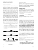
Table 2—Factory Default Settings Default PLACE CALIBRATION MAGNET HERE TO ACTIVATE INTERNAL REED SWITCH Configurable Options Gas Type Methane Ethane, Propane Butane, Propylene Special B2349 Figure 2—Location of Receiver's Internal Magnetic Switch Measurement Range (LFL-M) 0-5 0-2, 0-5 Low Alarm Threshold (LFL-M) 1 0.
Fault Indication Transmitter LAMP Operation Faults and status conditions are indicated using the 4‑20 mA analog signal output. Refer to Table 3. Signaling modes include two predefined and one user defined mode. OPGD-Rx mode (default) is available as well as a user defined mode for third party compatibility. Dual xenon lamps illuminate the linear detection path from the transmitter to the receiver.
Specifications CAUTION When the OPECL Gas Detector is used in conjunction with an appropriate certified Control Unit and configured for a non-latching high alarm, the control unit must always latch and require a deliberate manual action to clear a high gas alarm. When used as a stand alone device, the high alarm must always be programmed for latching operation. Input Voltage (Both Modules)— 24 Vdc nominal. Operating range is 18 to 30 Vdc. Ripple cannot exceed 0.5 volts P-P.
accuracy— Refer to the appropriate Appendix for details. HART COMMUNICATION PORT— An intrinsically safe port is provided on the receiver for connecting a Rosemount/Emerson HART Communicator. Note Misalignment will cause the manufacturer stated Accuracy limits to increase, but remain within the limits of EN 50241-1, -2, EN 60079-29-4, and IEC 60079-29-4. • Maximum separation distance between receiver and communicator is 610 meters.
Dimensions— Shipping Weight— Transmitter or receiver (replacement): 30 pounds (14 kg) Transmitter and receiver with mounting hardware: 75 pounds (34 kg) Module Length: 11.5 inches (29 cm) Diameter: 3.5 inches (9 cm) nominal 4.5 inches (11 cm) maximum warranty— 2 year limited warranty from date of manufacture. Mounting Plate Height: 14.5 inches (37 cm) Width: 6.5 inches (16 cm) Designed to attach to a 4 inch nominal diameter pipe. ± 8.
Important Safety Notes Installation CAUTION The wiring procedures in this manual are intended to ensure proper functioning of the system under normal conditions. However, because of the many variations in wiring codes and regulations, total compliance to these ordinances cannot be guaranteed. Be certain that all wiring complies with the NEC as well as all local ordinances. If in doubt, consult the authority having jurisdiction before wiring the system.
Consideration of the following system location guidelines is also recommended: Snow and Ice in Ambients Below –20°C The heated optics on both modules will melt snow or ice on the windows in ambient temperatures down to approximately –20°C. Below this temperature, snow or ice blown onto the window will not be melted until the ambient temperature rises.
Module Mounting Recommendations IMPORTANT In all cases, consider whether additional bracing or support is needed to ensure the structural integrity of the module installation. See Figure 4. Remember that accurate module alignment is essential for proper performance of an open path gas detection system, and even a small amount of movement can have a detrimental effect on alignment. This is especially true for installations with significant module separation distances.
Module mounting options include: a float-type battery charging system is recommended. If an existing source of 24 Vdc power is being utilized, verify that system requirements are met. • A vertical post with a nominal outside diameter of 4.5” (11.43 cm). Acceptable outside diameter range is 4.0 to 5.0 inches. See Figure 5. note If disconnection of power is required, separate disconnect capability must be provided. • For flat surface mounting, refer to Figure 6.
Power Wiring Size and Maximum Length optional relays 1. To ensure proper operation, OPECL power terminals (terminals 1 and 2 for Rx and Tx) and 4-20 mA terminals (terminals 6 and 7 for Rx) must receive 18 Vdc minimum. 24 Vdc is recommended. Terminals 1 and 4, and terminals 2 and 5 on the OPECL Rx are internally connected (see wiring diagrams). Optional relay contacts are “dry”, meaning that the installer must provide the voltage to the common terminal of the relay output.
wiring PROCEDURE For systems using conduit, modules must be wired using a short piece of suitable flexible conduit to allow optical alignment of the modules. Conductor insulation should be stripped off with a bare conductor length of 0.2 inch (5 mm) minimum and 0.7 inch (18 mm) maximum). Open Path Eclipse screw terminal torque range is 3.5–4.4 lb.-in. (0.4–0.5 N·m). –24 VDC 1 +24 VDC 2 3 4 5 6 Cable shield, if used, should be properly terminated.
–24 VDC 1 +24 VDC 2 CALIBRATE 3 –24 VDC 1 –24 VDC 4 +24 VDC 2 +24 VDC 5 CALIBRATE 3 –24 VDC 4 +24 VDC 5 + 4-20 MA 6 – 4-20 MA 7 RS-485 B 8 + 4-20 MA 6 – 4-20 MA 7 RS-485 B 8 RS-485 A 9 – 10 RS-485 A 9 FAULT (ORANGE) 11 RELAY POWER 10 LOW ALARM (WHITE) 12 FAULT 11 LOW ALARM 12 HIGH ALARM 13 RELAY POWER (RED) WIRING TO OPTIONAL RELAY BOARD NO USER CONNECTION 24 VDC HIGH ALARM (YELLOW) 13 + * 4 to 20 MA + – NO USER CONNECTION B2050 *TOTAL LOOP RESIST
24 VDC 24 VDC – – + –24 VDC 1 2 +24 VDC 2 CALIBRATE 3 CALIBRATE 3 –24 VDC 4 –24 VDC 4 +24 VDC 5 +24 VDC 5 + 4-20 MA 6 + 4-20 MA 6 – 4-20 MA 7 – 4-20 MA 7 RS-485 B 8 RS-485 B 8 RS-485 A 9 RS-485 A 9 RELAY POWER 10 RELAY POWER 10 FAULT 11 LOW ALARM 12 HIGH ALARM 13 –24 VDC 1 +24 VDC FAULT 4 to 20 MA + – * – 12 HIGH ALARM 13 24 VDC + – * 4 to 20 MA + – + 24 VDC 11 LOW ALARM + NO USER CONNECTION B2052 NO USER CONNECTION B2053 *TOTAL LOOP R
startup BASIC ALIGNMENT PROCEDURE When the OPECL is installed and wired as described in the “Installation” section, it is ready for commissioning. If the application requires that specific changes be made to the factory settings, HART communication will be required. Equipment Required 1. Properly installed and powered OPECL system (transmitter and receiver). Easy access to both modules is highly recommended. 2. Telescope Alignment Tool p/n 009104-001.
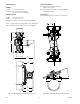
U-BOLT NUTS (2)* VERTICAL ADJUSTMENT BOLTS WITH LOCKING NUTS (2) OPECL MOUNTING BOLT* VERTICAL ALIGNMENT LOCKING NUTS (2) OPECL MOUNTING BOLT* HORIZONTAL ADJUSTMENT BOLTS WITH LOCKING NUTS (2) U-BOLT NUTS (2)* *TORQUE TO 20 FT-LBS B2302 Figure 18—OPECL Mounting and Alignment Hardware (Transmitter Module Shown) 6. Install the Telescope Alignment Tool onto the receiver module by inserting the captive thumbscrews into the threaded holes on the faceplate. See Figure 19.
STEP 1: CENTER CROSS HAIRS ON TARGET USING ADJUSTMENT BOLTS ON MOUNTING PLATE (POSITION A). STEP 2: ROTATE SCOPE 180°. ALIGNMENT ERROR CAUSES CROSS HAIRS TO MOVE TO POSITION B. STEP 3: ADJUST ALIGNMENT SCREWS ON SCOPE TO PLACE CROSS HAIRS AT POSITION C. STEP 4: ROTATE SCOPE 180° TO ORIGINAL POSITION. STEP 5: REPEAT STEPS 1 TO 4 UNTIL THE UNIT IS CORRECTLY ALIGNED.
Aperture Kit for Short Range Applications Recommendations for using the HART Field Communicator The Short Range Aperture Kit enables successful application of the OPECL gas detector at distances of approximately 5 to 30 meters. The kit is available in Delrin plastic (included with OPECL receivers) or optional stainless steel. • Ensure that the HART communicator is certified for use in classified areas. • The HART communication device must include the OPECL device descriptor (DD) software menu.
Note If a HART handheld communicator is not available, the alignment procedure can be performed in a limited way by monitoring the 4-20 mA output. (This method is only partially effective due to the deadband built into the 4-20 mA output.) If the partial beam blocks result in output deflection greater than 4.00 mA +/- 0.1, alignment should be adjusted to eliminate the deflection. The OPECL’s status LED can also be observed. The LED should remain green with the beam block in any position.
C. If adjustments to the receiver were necessary, perform a zero calibration and then repeat the sequence of partial beam blocks. Repeat the adjust, zero calibration, and recheck process until no adjustments to the receiver are necessary, and the partial beam block has little or no effect on the receiver under test. Gain Level Check (Optional) It is necessary to complete the alignment procedure before checking the gain level.
Calibration Digital Communication Calibration CALIBRATION OVERVIEW MODBUS communication may be utilized to initiate OPECL calibration (consult factory). Although routine calibration of the OPECL is normally not required, the device supports non-intrusive field zero calibration capability. Span calibration is not required. Detailed Calibration Procedure using Magnetic Switch Zero Calibration Zero Calibration 1. Apply magnet for 2 seconds minimum to initiate calibration.
Troubleshooting Optics Cleaning Cleaning of the OPECL optical surfaces is normally required only if an optical fault is indicated. A Fault status is indicated by a yellow LED and also by the 4 to 20 mA output. Refer to Table 5 for assistance in correcting malfunctions with the Open Path Eclipse Detector. Thoroughly douse both window surfaces using a liberal amount of isopropyl alcohol to clear away contaminant particles. Repeat the alcohol flush to remove any remaining contaminants.
replacing OPecl transmitter/ receiver electronics module Module Replacement Procedure Tools Required: – 4 mm hex wrench Warning Do not open when an explosive gas atmosphere may be present. – Torque wrench capable of accurately measuring 40 inch-pounds 1. Bypass system alarms as needed, then remove 24 Vdc power from the OPECL detector. Caution Only Det-Tronics authorized personnel are allowed to perform this repair. 2. Remove the four stainless steel flange bolts using a 4 mm hex wrench. See Figure 22.
transmitter, not on the receiver). If the separation distance is between 5 and 30 meters and signal saturation is indicated after completion of the Basic Alignment procedure, an aperture will be required (even if no aperture was originally installed). Refer to the "Aperture Kit for Short Range Applications" section in this manual for complete information regarding apertures. BULKHEAD OPECL MODULE A2500 ALIGNMENT PIN (2) 9. Perform a zero calibration of the detector.
ORDERING INFORMATION SPARE PARTS When ordering, please refer to the OPECL Model Matrix: alignment equipment Part Number 009104-001 009762-002 Description OPECL Alignment Telescope — Consists of a 32mm sighting device with 3-9x zoom magnifier that is factory assembled with precision holder and reflective mirror, and partial beam block tool. Partial Beam Block Tool (included with 009104-001) Part Number Description 102740-002 Calibration Magnet 005003-001 Silicone Free Grease 107427-040 O-Ring, 3.
OPECL MODEL MATRIX MODEL OPECL 10.
Appendix A FM Approval Description The following items, functions and options describe the FM approval. Approval Open Path Eclipse Infrared Hydrocarbon Gas Detector, Model OPECL Series. Class I, Div. 1, Groups B, C & D (T5) with intrinsically safe output for HART communication in accordance with control drawing 007722-001 (see Appendix G). Class I, Div. 2, Groups A, B, C & D (T4). NEMA/Type 4X. Conduit seal not required. Performance verified in accordance with FM 6325, ANSI/ISA 12.13.04.
Appendix B CSA certification Description The following items, functions and options describe the CSA approval. Approval Open Path Eclipse Infrared Hydrocarbon Gas Detector, Model OPECL Series. Class I, Div. 1, Groups B, C & D (T5) with intrinsically safe output for HART communication in accordance with control drawing 007722-001 (see Appendix G). Class I, Div. 2, Groups A, B, C & D (T4). Type 4X. Conduit seal not required.
Appendix C ATEX Approval Description The following items, functions and options describe the ATEX approval. Approval Open Path Eclipse Infrared Hydrocarbon Gas Detector, Model OPECL Series. Receiver Transmitter 0539 II 2 G 0539 II 2 G DEMKO 06 ATEX 141002X DEMKO 06 ATEX 141002X Ex d e [ib] IIC T5 Gb Ex d e IIC T5 Gb T5 (Tamb –50°C to +60°C) T5 (Tamb –50°C to +60°C) EN 60079-29-4 IP66/IP67. IP66/IP67.
ATEX Special Conditions for Safe Use for the [ib] HART communication port only: • The intrinsically safe output on the HART Communicator Port is internally connected to frame. • Um is restricted to 250 V, prospective short circuit current < 1500 A. • When connecting to a circuit using up to 1% of Co or Lo, then the C or L is limited to the Co and Lo listed above. If either the C or L is above 1% of Co or Lo, then C or L are each limited to 50% of the Co or Lo listed above.
Accuracy (per EN 60079-29-4) 4-20 mA Model: ±0.25 LFL-meters or ±12.4% of applied gas concentration, whichever is greater, with water vapor @ ≥82°C. LON Model: ±0.25 LFL-meters or ±15.2% of applied gas concentration, whichever is greater, @ –55°C. response time 4-20 mA Model T50: 1.2 seconds (2.5 LFL-meters applied) T90: 2.5 seconds (2.5 LFL-meters applied). EQP Model T90: 5.3 seconds* (2.5 LFL-meters applied).
Appendix D IECEx Approval Description The following items, functions and options describe the IECEx approval. Approval Open Path Eclipse Infrared Hydrocarbon Gas Detector, Model OPECL Series. Receiver Transmitter IECEx ULD 05.0001X IECEx ULD 05.0001X Ex d [ib] IIC T5 Gb Ex d IIC T5 Gb T5 (Tamb –55°C to +60°C) T5 (Tamb –55°C to +60°C) --OR---OR-Ex d e [ib] IIC T5 Gb. Ex d e IIC T5 Gb. T5 (Tamb –50°C to +60°C) T5 (Tamb –50°C to +60°C) IP66/IP67. IP66/IP67. HART Communication Port: Uo = 4.
Special Conditions for Safe Use for the [ib] HART communication port only: • The intrinsically safe output on the HART Communicator Port is internally connected to frame. • When connecting to a circuit using up to 1% of Co or Lo, then the C or L is limited to the Co and Lo listed above. If either the C or L is above 1% of Co or Lo, then C or L are each limited to 50% of the Co or Lo listed above. • Um is restricted to 250 V, prospective short circuit current < 1500 A.
Appendix E Other Approvals The following items, functions and options describe various other approvals applicable to the Model OPECL. SIL Approval IEC 61508 Certified SIL 2 Capable. Applies to specific models – refer to the Safety Reference Manual (form 95-8665) for details. INMetro (Brazil) Certificate No. UL-BR 12.
Appendix F HART Communication Digital communication with the Open Path Eclipse is necessary to monitor internal status and to modify the factory settings. This appendix provides guidance on establishing HART communication, and describes the communication menu structure when using the Open Path Eclipse with the HART Handheld Communicator. interconnecting the HART communicator with the Open Path Eclipse Unscrew the protective cap from the HART communication port on the side of the Open Path Eclipse receiver.
Open Path Eclipse HART Menu Structure This section displays the menu trees for the Open Path Eclipse. The Menu tree shows the primary commands and options available when using menu selections. OPGD RX Root Menu 1) Process Menu 2) Status Menu 3) Setup Menu 4) Calibration Menu 5) Test Menu Process Menu 1) Gas Name 2) PV. Digital Value 3) PV. Analog Value 4) PV.
Protect Menu ment Status Menu arm Menu gh Alarm Level gh Alarm Latch w Alarm Level w Alarm Latch t Menu ce Alignment Alignment 4) Date 5) Month 6) Day 7) Year Connections and Hardware 8) Write Protect The HART Communicator can interface with the Open Path Eclipse from the onboard I.S. communication port, from the control room, or from any wiring termination point in the analog output signal loop.
appendix G Control drawing 10.
Appendix H Eagle Quantum Premier compatible OPECL installation and wiring The Eagle Quantum Premier (EQP) version of the Model OPECL Open Path Eclipse uses the identical installation procedure, device location guidelines, and power supply requirements as described in the “Installation” section of this manual. Refer to the EQP version wiring diagram for specific wiring termination guidance.
Configuration and Operation Configuration of the EQP OPECL is accomplished using Det-Tronics Safety System Software (S3) that is running on the EQP Operator Interface Station (OIS). OnBoard HART Port The on-board HART port is functional on the EQP OPECL, however, it should not be used for device configuration purposes. All EQP device configuration should be performed using the S3 program. Multi-Colored LED Operation of the status indicating LED is identical to all other OPECL versions.
Setting network addresses Overview of Network Addresses Each OPECL receiver on the EQP LON must be assigned a unique address. (Since transmitters do not reside on the LON, no network address switch setting is needed.) Addresses 1 to 4 are reserved for the EQP controller. Valid addresses for field devices including OPECL gas detectors are from 5 to 250. IMPORTANT If the address is set to zero or an address above 250, the system will ignore the switch setting and the device.
Do not assign duplicated addresses. Duplicated addresses are not automatically detected. Modules given the same address will use the number given and report to the controller using that address. The status word will show the latest update, which could be from any of the reporting modules using that address. After setting address switches, record the address number and device type on the “Address Identification Chart” (form 95-8487).
Switch Access Procedure NOTE It is strongly recommended to document all OPECL gas detector network addresses as well as the addresses of all other LON devices on the Address Identification Chart before disassembling and programming the OPECL gas detectors. Removal of four stainless steel flange bolts and the front electronic module of the OPECL receiver from the bulkhead is required in order to gain access to the network address DIP switch.
10.
95-8556 FlexSonicTM Acoustic Leak Detector X3301 Multispectrum IR Flame Detector Corporate Office 6901 West 110th Street Minneapolis, MN 55438 USA www.det-tronics.com PointWatch Eclipse ® IR Combustible Gas Detector Phone: 952.946.6491 Toll-free: 800.765.3473 Fax: 952.829.8750 det-tronics@det-tronics.com FlexVu ® Universal Display with GT3000 Toxic Gas Detector Eagle Quantum Premier ® Safety System All trademarks are the property of their respective owners. © 2013 Detector Electronics Corporation.