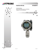
Instructions 95-8670 Nanotechnology Metal Oxide Semiconductor (NTMOS) IP66/IP67 H2S Gas Detector 2.
Table Of Contents APPLICATION . . . . . . . . . . . . . . . . . . . . . . . . . . . . . . . . . . . . . . . . . . . . 1 FEATURES . . . . . . . . . . . . . . . . . . . . . . . . . . . . . . . . . . . . . . . . . . . . . . 1 DESCRIPTION . . . . . . . . . . . . . . . . . . . . . . . . . . . . . . . . . . . . . . . . . . . 1 Detector Output . . . . . . . . . . . . . . . . . . . . . . . . . . . . . . . . . . . . . . . .
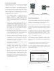
INSTRUCTIONS Nanotechnology Metal Oxide Semiconductor (NTMOS) IP66/IP67 H2S Gas Detector CAUTION Be sure to read and understand the entire instruction manual before installing or operating the gas detection system. This product is intended to provide early warning of the presence of H2S gas. Proper device installation, operation, and maintenance is required to ensure safe and effective operation. If this equipment is used in a manner not specified in this manual, safety protection may be impaired.
DETECTOR OUTPUT U9500 Infiniti Transmitter The non-isolated 4-20 mA dc drive circuitry is rated at a maximum 600 ohms loop resistance with 24 Vdc supply voltage. The U9500B Infiniti® transmitter is a single channel device. In addition to the standard 4-20 mA analog signal output, the U9500B offers 4 optional relay outputs for fault and alarm indications. The 4 outputs are: fault, high alarm, low alarm, and auxiliary alarm. The relays have form C (SPDT) contacts.
DETECTOR POSITIONING Proper detector location is essential for providing maximum protection. The most effective number and placement of detectors varies depending on the conditions at the job site. The individual designing the installation must rely on experience and common sense to determine the number of detectors needed and the best locations to adequately protect the area.
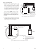
INSTALLATION AND WIRING 1. Determine the best mounting locations for the detector. Mount the detector with the sensing element pointing down (18 inches from surfaces below). The junction box (GDTB or transmitter housing) is intended for flat-surface mounting, such as on a wall or post. A spacer or stand-off (1/4 to 1/2 inch) may be needed to allow adequate clearance for the detector and calibration cup. The junction box should be electrically connected to earth ground.
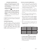
3. Confirm that the power and signal cabling for the gas detector is the proper size and type, and is appropriate for the application requirements. After all electrical connections are made, double check the terminations against the wiring diagrams to ensure that all connections are properly terminated. INFINITI TRANSMITTER NO COM NC FAULT RELAY – + POWER S 4. The NTMOS Detector is designed to operate at 24 Vdc nominally.
STARTUP PROCEDURE CALIBRATION FREQUENCY OF CALIBRATION WARNING Ensure that any output loads actuated by the detection system are bypassed to prevent accidental or unnecessary activation of these devices. The calibration frequency required in different applications can vary depending upon the amount of background gas, concentration of H2S, and ambient environmental conditions. Calibration must be performed: — When a new system is initially put into service. — When the detector is replaced.
IMPORTANT CALIBRATION NOTES Calibrating a Stand-Alone NTMOS Detector 1. A dc current meter capable of measuring 4-20 mA must be connected to the current loop output. This can be accomplished by connecting a dc ammeter in series with the load or by connecting a digital dc voltmeter across a known load resistance and calculating the current flow using the formula: current (I) = voltage/load resistance.
MAINTENANCE The NTMOS H2S Detector must be “functional tested” using only Det-Tronics’ humidification tube kit or the ampoule kit. All ampoule functional tests must be performed using the Det‑Tronics H2S Mixer with thumb screw ampoule breaker and internal mixing fan (p/n 007067-001). When using either method to perform a bump test do not use bottled H2S with nitrogen. When performing calibrations, validate the expiration date of the gas cylinder.
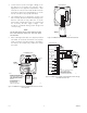
FILTER REPLACEMENT IMPORTANT A hydrophobic filter must be installed to maintain the IP66/IP67 Ingress Protection rating. If a filter is not installed, the detector assumes an IP53 rating. INCORRECT CORRECT The hydrophobic filter provides protection against the ingress of dust and water, while permitting free flow of gas to the H2S sensor. The filter assembly is field replaceable.
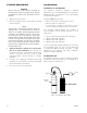
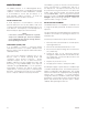
2.0 (5.0) 1.75 (4.5) 3/4 INCH NPT / M25 THREAD 4.3 (11.0) A2569 MOUNT 18” (TYPICAL) FROM SURFACES BELOW Figure 10—Dimensions of NTMOS Detector in Inches (Centimeters) 3.9 (9.9) 8.8 (22.4) 3.3 (8.4) 4.4 (11.2) 8.0 (20.3) A2455 Figure 11—Dimensions of NTMOS Detector with Ampoule Calibration Kit with Mixer Attached in Inches (Centimeters) 2.
SPECIFICATIONS CALIBRATION CYCLE— • 30 days after initial calibration CURRENT OUTPUT— 4-20 mA. • MEASUREMENT RANGE— 0 to 100 ppm. Every 90 days thereafter, or as required by the application and environment. INPUT VOLTAGE— 18 to 30 Vdc, 24 Vdc nominal. DIMENSIONS— See Figure 10 for NTMOS Detector See Figure 11 for the NTMOS Detector with Calibration Gas Mixer attached. INPUT POWER— 2.5 watts maximum. ENCLOSURE MATERIAL— 316 Stainless Steel.
DEVICE REPAIR AND RETURN Prior to returning devices, contact the nearest local Detector Electronics office so that a Return Material Identification (RMI) number can be assigned. A written statement describing the malfunction must accompany the returned device or component to assist and expedite finding the root cause of the failure. Transmitter: U9500B Infiniti, Specify with/without relays, aluminum or stainless steel housing. Display Unit: FlexVu UD10, Includes relays, 4-20 mA w/HART.
APPENDIX A FM APPROVAL NOTE The NTMOS Gas Detector is designed and approved as a ‘stand alone’ toxic gas detector. Hazardous Location Class I, Division 1, Groups B, C, D Class I, Division 2, Groups A, B, C, D –40°C to +65°C (Performance verified) –40°C to +75°C (Haz Loc Rating) IP66/IP67 (with hydrophobic filter) IP53 (without hydrophobic filter) Performance tested to ANSI/ISA-92.0.01 – Sample of test requirements Gas Detected ANSI/ISA 92.0.01: 1998 (App.
APPENDIX B CSA APPROVAL NOTE The NTMOS Gas Detector is designed and approved as a ‘stand alone’ toxic gas detector. PRODUCTS CLASS 4828 02 – SIGNAL APPLIANCES - Toxic Gas Detection Instrument - For Hazardous Locations Class I, Div. 1, Groups B, C & D (T5); Class I, Div. 2, Groups A, B, C & D (T5); IP53 without Filter, IP66 / IP67 with Filter. NTMOS H2S Toxic Gas Detector , Model NTM Series, input voltage 18-30 Vdc maximum and 2.5 W maximum, output rated 4-20 mA, Tamb= –40°C to +75°C (Haz Loc Rating).
APPENDIX C ATEX / CE APPROVAL NOTE The NTMOS Gas Detector is designed and approved as a ‘stand alone’ toxic gas detector. Hazardous Location ATEX: 0539 II 2 G Ex d IIC T5 Gb FM09ATEX0063X T5 (Tamb= –40°C to +65°C) IP66/IP67 (with hydrophobic filter and sinter guard) IP63 (without hydrophobic filter). FM ® APPROVED EN Standards: EN 50270: 2006 EN 60079-0: 2009 EN 60079-1: 2007 EN 60529: 1991+ A1 2000.
APPENDIX D ADDITIONAL APPROVALS Hazardous Location CEPEL 10.1964X Ex d IIC T5 Gb IP66 T5 (Tamb = –40°C to +65°C) IP63/IP66/IP67 IEC Standards: IEC 60079-0: 2007 IEC 60079-1: 2007 IEC 60529: 01. Mechanical Model with or without filter assembly NOTE For use with the GDTB, all cable entry devices shall be Brazil certified in the type of explosion protection, flameproof enclosure ‘d’, suitable for the conditions of use and correctly installed with an ingress protection rating of IP66/IP67.
95-8670 Detector Electronics Corporation 6901 West 110th Street Minneapolis, MN 55438 USA X3301 Multispectrum IR Flame Detector PointWatch Eclipse® IR Combustible Gas Detector FlexVu® Universal Display w/ GT3000 Toxic Gas Detector Eagle Quantum Premier® Safety System T: 952.941.5665 or 800.765.3473 F: 952.829.8750 W: http://www.det-tronics.com E: det-tronics@det-tronics.