
Manual

7
9.1 95-8616
DETECTOR INSTALLATION
3/4"NPTmodelshaveTaperedThreadsandnoLock
Nut.Installthesensorasfollows:
1. Screw the detector into the appropriate entry on
the termination box. Ensure a minimum of 5 fully
engagedthreads.UseofteontapeonNPTthreads
is recommended to prevent thread damage.
2. When the detector gets tight, note the position of the
LEDs,GNDlugandcalibrationnotchandadjustthe
detector as required so that the LEDs will be easily
visible.
M25 Models
M25 models have Straight Threads and a Lock Nut.
Install the detector as follows:
1. Screw the detector lock nut as far back as it will go,
then screw the detector into the appropriate entry
on the termination box. Ensure a minimum of 7 fully
engaged threads.
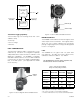
2. With the detector in the desired position (LEDs
visible as shown in Figure 5), tighten the lock nut
against the termination box to hold the detector
securely in place.
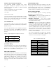
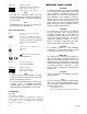
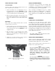
3. Tighten the set screws (minimum of two) to prevent
movement of the lock nut. See Figure 6.
A Det-Tronics sensor termination box (Model STB)
is required for installing the sensor in a stand alone
configuration, or for installing the GT3000 remotely
from the UD10/UD20 Universal Display Unit.
When installing the GT3000 remotely from a UD10/
UD20, two-conductor shielded cable is required to
prevent possible nuisance EMI/RFI. The maximum
cable length between the GT3000 and the UD10/UD20
is 2000 ft.
WirinG
Calculate the total gas detection system power
consumption rate in watts from cold start-up. Select a
power supply with adequate capability for the calculated
load. Ensure that the selected power supply provides
sufficient regulated and filtered output power for the
entire system. If a back-up power system is required, a
float-type battery charging system is recommended. If
an existing source of power is being utilized, verify that
system requirements are met.
NOTE
The power supply must also meet the noise
requirements for HART systems.
Always use proper cabling type and diameter for input
power as well as output signal wiring. 22 to 14 AWG
shielded stranded copper wire is recommended.
Always install a properly sized, master power fuse or
breaker on the system power circuit.
NOTE
The use of shielded cable in conduit or shielded
armored cable is highly recommended. In
applications where the wiring is installed in
conduit, dedicated conduit is recommended.
Avoid low frequency, high voltage, and
non-signaling conductors to prevent nuisance
EMI problems.
CAUT ION
The use of proper conduit installation techniques,
breathers, glands, and seals is required to prevent
water ingress and/or maintain the explosion-proof
rating.
Set Screws
Figure 6—Location of Lock Nut and Set Screws
(Metric Models Only)