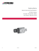
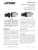
Instructions Electrochemical Gas Detector GT3000 Series Includes Transmitter (GTX) and Sensor Module (GTS) 9.
Table of Contents Description . . . . . . . . . . . . . . . . . . . . . . . . . . . . . 1 GTS Sensor Module . . . . . . . . . . . . . . . . . . . . . . GTX Transmitter . . . . . . . . . . . . . . . . . . . . . . . . . Real Time Clock . . . . . . . . . . . . . . . . . . . . . . . . . History/Event Logs . . . . . . . . . . . . . . . . . . . . . . . HART Communication . . . . . . .
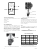
INSTRUCTIONS Electrochemical Gas Detector GT3000 Series Includes Transmitter (GTX) and Sensor Module (GTS) Sensor Module (GTS) Transmitter (GTX) Important Be sure to read and understand the entire instruction manual before installing or operating the gas detection system. This product is intended to provide early warning of the presence of a toxic or explosive gas mixture, or of oxygen depletion. Proper device installation, operation, and maintenance are required to ensure safe and effective operation.
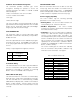
Automatic Sensor Module Recognition HISTORY/Event Logs The transmitter provides automatic gas sensor recognition, allowing the operator to access the following information via HART, or a UD10 or UD20 Universal display: • Date of manufacture of the sensor module Both the transmitter and sensor are able to store 256 history logs, which are saved in non-volatile memory and retained through power cycles.
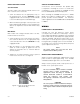
GT3000 Gas Detector Transmitter RTC HART Interface Event Logs Transmitter updates sensor module time / date Transmitter reads calibration logs from sensor Sensor Module Calibration Logs GREEN LED (ON) YELLOW LED (OFF) Figure 1—GT3000 Logging A2450 Transmitter Logging Capability Figure 3— Location of LEDs on GT3000 Gas Detector The transmitter logs the following events with a time and date stamp: Magnetic Switch The GT3000 is furnished with an internal magnetic reed switch as part of the user in
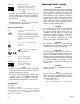
specifications 6.2 (15.8) 5.6 (14.3) sensor and transmitter Available Sensors— Refer to Appendix A. 2.5 (6.4) Cross Sensitivity— See Appendix A for Cross Sensitivity information. B2397 calibration— Sensors are calibrated at the factory. Gas type and range are read by the transmitter. Field calibration is initiated at the detector, at the UD10/UD20 Universal Display Unit, or by some other HART interface device. Figure 4—Dimensions of GT3000 Gas Detector in Inches (CM) Pressure range— Atmospheric ±10%.
INMETRO: Important Safety Notes CEPEL 10.1927X Ex d mb [ia Ga] IIC T4 Gb IP66 Tamb –40°C to +50°C (H2S) Tamb –20°C to +50°C (CGS) CAUTION The wiring procedures in this manual are intended to ensure proper functioning of the device under normal conditions. However, because of the many variations in wiring codes and regulations, total compliance to these ordinances cannot be guaranteed. Be certain that all wiring complies with the NEC as well as all local codes.
Installation The most effective number and placement of detectors varies depending on the conditions on site. The individual designing the installation must often rely on experience and common sense to determine the detector quantity and best locations to adequately protect the area. Note that it is typically advantageous to locate detectors where they are accessible for maintenance. Locations near excessive heat or vibration sources should be avoided if possible.
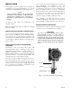
Detector installation SENSOR termination box A Det-Tronics sensor termination box (Model STB) is required for installing the sensor in a stand alone configuration, or for installing the GT3000 remotely from the UD10/UD20 Universal Display Unit. 3/4" NPT Models 3/4" NPT models have Tapered Threads and no Lock Nut. Install the sensor as follows: 1. Screw the detector into the appropriate entry on the termination box. Ensure a minimum of 5 fully engaged threads.
Intrinsic SafeTy Barriers Guidelines for Intrinsic Safety Wiring When the GT3000 is used in an intrinsically safe installation, care must be taken when selecting an I.S. barrier to ensure proper function of the device. The GT3000 has been tested with the types of barriers listed in Tables 3 and 4. Intrinsically safe systems must be installed in accordance with the approved control drawings for the field equipment and the intrinsic safety barriers.
SENSOR TERMINATION BOX GREEN + RED 24 VDC AC K RE D BLACK RED BL SEE NOTES 2 & 3 – SEE NOTE 1 BLACK NOTE 1 GROUND THE SHIELD AT THE POWER SOURCE END ONLY. NOTE 2 250 OHM RESISTOR REQUIRED FOR HART MENU ACCESS. NOTE 3 EXTERNAL HART COMMUNICATION DEVICES CAN BE CONNECTED ACROSS THE 250 OHM RESISTOR OR ACROSS THE GT3000. NOTE 4 JUNCTION BOX MUST BE ELECTRICALLY CONNECTED TO EARTH GROUND.
UD20 DISPLAY UNIT + + J2-6 – J2-5 SHIELD J2-4 POWER LOOP 24 VDC SEE NOTES 2 & 3 – SEE NOTE 5 RED BLACK GREEN J2-3 + J2-2 – J2-1 SHIELD SENSOR LOOP SEE NOTE 1 J2 GT3000 GAS DETECTOR NOTE 1 CONNECT THE GREEN DETECTOR LEAD TO THE CHASSIS GROUND LUG ON THE INSIDE BOTTOM OF THE UD20 DISPLAY UNIT ENCLOSURE. NOTE 2 250 OHM RESISTOR REQUIRED FOR HART MENU ACCESS.
NON-HAZARDOUS LOCATION HAZARDOUS LOCATION BLACK RED UD10 DISPLAY UNIT GREEN J3-2 J3-3 J3-4 J3-5 24 VDC – 4-20 mA 24 VDC + 4-20 mA – J3-1 4-20 mA + P1-2 J3 SEE NOTE 1 HIGH ALARM COM J4-1 SHIELD P1-1 HIGH ALARM NC J4-2 HIGH ALARM NO J4-3 AUX ALARM COM J4-4 AUX ALARM NC J4-5 AUX ALARM NO J4-6 LOW ALARM COM J4-7 LOW ALARM NC J4-8 LOW ALARM NO J4-9 FAULT COM J4-10 P1 24 VDC + SHIELD P2-1 P12 P2-2 + 24 VDC – MODBUS Connector P2-3 RS485 B SHIELD 24 VDC RS485 A J2-1
Calibration The calibration process proceeds automatically after initiation. Onboard LEDs signal the operator when to apply the calibration gas and inform of the progress. GT3000 Calibration The GT3000 supports one person calibration, which can be initiated locally using a calibration magnet, or remotely with a command from the HART interface. The calibration process is automatic, with the exception of gas delivery.
Calibration Procedure NOTE The calibration procedure must be completed within a ten minute period. If the calibration is not completed, a calibration fault will be generated and the transmitter will continue to use the previous calibration data. note When attaching or removing the calibration cup, push or pull the cup with a slight clockwise twist. Turning counterclockwise can cause the filter assembly on the GT3000 to loosen.
Maintenance Important Always exercise caution when working in combustible gas areas. Follow replacement instructions explicitly. note Refer to the GT3000 Safety Manual (number 9 5 - 8 6 8 5 ) fo r s p e c i fi c re q u i re m e n t s a n d recommendations applicable to the proper installation, operation, and maintenance of all SIL‑Certified GT3000 gas detectors. note Removing the sensor module with power applied will result in a fault condition until a new sensor module of the same type is installed.
DEVICE REPAIR AND RETURN Calibration Kits for Gas Sensors Part Number Gas / Concentration 010274-001 H2S / 10 ppm 010274-002 H2S / 25 ppm 010274-003 H2S / 50 ppm 010274-008 H2 / 500 ppm 010274-009 O2 / 20.9% 010274-010 CO / 50 ppm 010274-011 CO / 250 ppm 010274-005 NH3 / 50 ppm 010274-006 NH3 / 250 ppm 010274-013 SO2 / 10 ppm 010274-014 SO2 / 50 ppm 010274-004 Cl2 / 5 ppm 010274-016 NO2 / 10 ppm Replacement gas cylinders for all calibration kits are available.
GTS Sensor Model Matrix MODEL GTS DESCRIPTION Gas Sensor Module TYPE H2S CL2 GAS / RANGE Hydrogen Sulfide 20P 0 - 20 PPM 50P 0 - 50 PPM 100P 0 - 100 PPM Chlorine 10P NH3 H2 0 - 10 PPM Ammonia 100P 0 - 100 PPM 500P 0 - 500 PPM Hydrogen 1000P O2 0 - 1000 PPM Oxygen 25V CO SO2 NO2 0 - 25 % by Vol Carbon Monoxide 100P 0 - 100 PPM 500P 0 - 500 PPM Sulfur Dioxide 20P 0 - 20 PPM 100P 0 - 100 PPM Nitrogen Dioxide 20P 0 - 20 PPM TYPE APPROVAL* B INMETRO (Brazil) C CSA D DNV
GTX Transmitter Model Matrix MODEL DESCRIPTION GTX Gas Transmitter TYPE S MATERIAL Stainless Steel (316) TYPE THREAD SIZE N 3/4" NPT M Metric M25 TYPE OUTPUTS 26 4-20 mA, HART (3.6 mA FAULT) 29 4-20 mA, HART (2.45 mA FAULT) TYPE APPROVALS B INMETRO (Brazil) R Russia W FM/CSA/ATEX/CE/IECEx TYPE CLASSIFICATION (Division/Zone) 4 Intrinsically Safe 5 Explosion-Proof Note: Approvals Type W and B are SIL 2 Capable when used with an H2S or O2 GTS sensor module. 9.
Appendix A Sensor comparison/Cross Sensitivity Factory Mutual Performance Approved Electrochemical Gas Sensors Gas Range Response Time* Accuracy of Reading Hydrogen Sulfide (H2S) 0-20 PPM T50 = 10 Sec. T90 = 23 Sec. Hydrogen Sulfide (H2S) 0-50 PPM Hydrogen Sulfide (H2S) Operating Temperature Range Zero Drift Performance Approved Standard ±2 ppm or ±10% of Reading –40°C to +50°C ± 1 ppm/Mo. ISA 92.00.01 T50 = 10 Sec. T90 = 23 Sec. ±2 ppm or ±10% of Reading –40°C to +50°C ± 1 ppm/Mo.
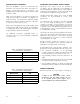
Typical Cross Sensitivity of NH3 Sensor (0-500 ppm) Typical Cross Sensitivity of NH3 Sensor (0-100 ppm) Gas Concentration Reading Gas Concentration Reading Alcohols 1000 ppm 0 ppm Alcohols 1000 ppm 0 ppm Carbon dioxide 5000 ppm 0 ppm Carbon monoxide 100 ppm 0 ppm Carbon monoxide 100 ppm 0 ppm Chlorine 5 ppm 0 ppm Hydrocarbons % Range 0 ppm Nitrogen dioxide 10 ppm 0 ppm Hydrogen 10000 ppm 0 ppm Sulfur dioxide 20 ppm –40 ppm Hydrogen sulfide 20 ppm ~ 2 ppm1 Hydrogen 3
Appendix B HART Communication HART MENU STRUCTURE This section displays the menu tree for the GT3000. The menu tree shows the primary commands and options available when using menu selections of a HART handheld communicator. 9.
9.
Appendix C ConTrol Drawing — FM 009803-001 Rev. D 9.
ConTrol Drawing — CSA 009803-002 Rev. B 9.
95-8616 FlexSonicTM Acoustic Leak Detector X3301 Multispectrum IR Flame Detector Corporate Office 6901 West 110th Street Minneapolis, MN 55438 USA www.det-tronics.com PointWatch Eclipse ® IR Combustible Gas Detector Phone: 952.946.6491 Toll-free: 800.765.3473 Fax: 952.829.8750 det-tronics@det-tronics.com FlexVu ® Universal Display with GT3000 Toxic Gas Detector Eagle Quantum Premier ® Safety System All trademarks are the property of their respective owners. © 2013 Detector Electronics Corporation.