
User Manual


1. 1 12
ALARMS
IMPORTANT
Alarm setpoints are specified at the time of
order placement with a conguration worksheet
(see Appendix A). If the alarm setpoints are not
specied at the time of order, the factory defaults
will be assumed (see "Default Setup Settings" in
the Setup section of this manual).
NOTE
All fault and alarm conditions are set for latching
on the HMI touchscreen. When active fault and
alarm conditions have been satised, press the
RESET button to clear all active conditions.
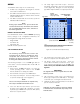
The GP16XX is programmed to indicate low and high
alarms. When a low alarm is generated, it is indicated
on the Main screen when a channel is flashing with red
(Figure 15). Low alarms are indicated on the Point Display
when the "Low Alarm" indicator is solid red (Figure 16).
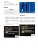
High alarms are indicated on the Main screen when
a channel changes to solid red . The Point Display
indicates high alarms when the "High Alarm" indicator is
solid red (Figure 17).
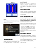
Latched alarms are indicated on the Main screen when
the Custom Device ID is surrounded by a solid red
border (Figure 18). This indication will remain visible until
the alarm condition is investigated, corrected, and the
RESET button is pressed.