Instructions 95-8671 Det-Tronics ® Standard Gas Panel 1.
Table Of Contents Description . . . . . . . . . . . . . . . . . . . . . . . . . . . . . . . . . . . . . . . . . . . . 1 Features AND BENEFITS. . . . . . . . . . . . . . . . . . . . . . . . . . . . . . . . . . 1 Enclosure . . . . . . . . . . . . . . . . . . . . . . . . . . . . . . . . . . . . . . . . . . . . . 1 SYSTEM COMPONENTS. . . . . . . . . . . . . . . . . . . . .
INSTRUCTIONS Det-Tronics ® Model GP16XX Gas Panel WARNING Be sure to read and understand the entire instruction manual before attempting to setup and operate the GP16XX Gas Panel. Proper device setup, operation, and maintenance is required to ensure safe and effective operation. If this equipment is used in a manner not specified in this manual, safety protection may be impaired.
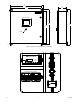
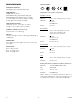
24.0 (60.96) 6.40 (16.2) 22.62 (57.45) R DETECTOR ELECTRONICS CORP. 6901 W. 110TH ST, MINNEAPOLIS, MN 55438 USA 1-800-468-3244 HMI TOUCH SCREEN 25.5 (64.9) 24.0 (60.96) 26.2 (66.
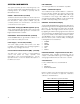
System Components Field Devices The following field devices are GP16XX compatible: The system has three (3) main component groups – the System Controller, LON, and 4-20 mA field devices. The following devices are included (or optional) with the GP16XX Gas Panel. PIRECL – PointWatch Eclipse® The PointWatch Eclipse Model PIRECL is a diffusionbased, point-type infrared gas detector that provides continuous monitoring of combustible hydrocarbon gas concentrations in the range of 0 to 100% LFL.
Important safety notes Installation The panel must be securely bolted in place in a nonhazardous area (indoors). Caution The wiring procedures in this manual are intended to ensure proper functioning of the device under normal conditions. However, because of the many variations in wiring codes and regulations, total compliance to these ordinances cannot be guaranteed. Be certain that all wiring complies with the NEC (National Electric Code) as well as all local ordinances.
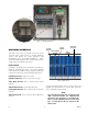
Figure 3—LON Wiring Terminal CUSTOM DEVCE ID Operator interface LOGIC DEFINED TAGNAME The HMI touch screen is located on the front of the enclosure door, and consists of several graphical screens that permit the setup, operation, and interrogation of the connected field devices. These screens include the Main screen, Setup screen, Device Setup screen, and Event Log screen.
The buttons along the bottom (SETUP, FAULT, EVENT LOGS, SILENCE, RESET) allow the user to interact with the system to perform various tasks. CONFIGURED CHANNEL (Tagname & Device ID are bolded white) UNCONFIGURED CHANNEL (Tagname & Device ID are grayed out) Their functions are as follows: SETUP opens the Setup screen (Figure 6) for configuring devices on the system. FAULT is solid yellow when a fault is present. When pressed, the Event Log screen is opened (Figure 9).
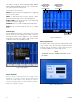
Device Setup screen Event Log Screen Devices are setup for use in the Device Setup screen (Figure 8). This screen is opened after the user ID and password have been correctly entered. The three text fields along the top are intended for displaying the channel name, custom device ID, and network address of a given device. Fault and alarm events are date and time stamped on the Event Log screen (Figure 9). Event logs residing on a blue background indicate active conditions that need to be investigated.
Specifications Certification— Operating VOLTAGE— 120-220 Vac input, 24 Vdc @ 10A output. FM ® APPROVED Components— EQ3001 EQP Controller EQ3710 AIM Analog Input Module (Optional) EQ2220 GFM Ground Fault Monitor (Included) 5.7” Human Machine Interface (HMI) - Included 24 Vdc, 10A Power Supply (Included). Certification of the system's components: EQ3001 Controller FM/CSA: Class I, Div.
SETUP 5. The Setup Login screen will re-open. Touch the "Password" input field to open the Password Input screen (Figure 10). Using the on-screen keyboard, type "DEC" and press ENT to accept the password. The GP16XX can be setup in one of three ways: 1. An EQP only configuration, allowing all 16 channels to be used for LON devices. 2. One AIM mounted inside the enclosure that powers 8 individual 4-20 mA devices, with the other 8 channels used for LON devices.
LON DEVICE SETUP CAUTION When the ECLIPSE Gas Detector is used in conjunction with an appropriate certified Control Unit and is setup for a non-latching high alarm, the control unit must always latch and require a deliberate manual action to clear a high gas alarm. When used as a stand alone device, the high alarm must always be programmed for latching operation. The following example is for an ECLIPSE gas detector setup for use on the LON.
Operation note A fte r c o n fi g u r i n g a d ev i c e , i t i s h i g h ly recommended that calibration be performed before operation. Calibration iMportant The Calibration Active and Calibration Fault indications are only available for LON devices, and not for 4-20 mA devices. The following instructions are specific to LON based devices.
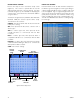
Figure 14—Fault Indication on Main Screen Figure 16—Low Alarm Indication on Point Display ALARMS High alarms are indicated on the Main screen when a channel changes to solid red . The Point Display indicates high alarms when the "High Alarm" indicator is solid red (Figure 17). Important Alarm setpoints are specified at the time of order placement with a configuration worksheet (see Appendix A).
Maintenance LATCHED ALARM INDICATION Depending on the environment, the GP16XX does not require specific maintenance, but the HMI touch screen may become dirty and cause visibility problems. Avoid using any solvent when cleaning a dirty panel. A damp cloth is sufficient for wiping dirt from the HMI touch screen. Replacement Parts The GP16XX devices are not designed to be repaired in the field. If a problem should develop, first carefully check for proper wiring, programming and calibration.
APPENDIX A – CONFIGURATION WORKSHEET The purpose of the configuration worksheet is to establish user defined parameters prior to the shipment of the GP16XX Gas Panel. Using the information collected from the worksheet, the packaged system solution will be shipped from the factory pre-configured with all the options selected by the user. Field devices are ordered separately. A PDF copy of the configuration worksheet can be found on our website. Note The worksheet must be completed during order placement.
1.1 CAL +24 4-20 RET 15 7 12 CHANNEL 3 COMMON 4-20 MA IN CHANNEL 7 11 COMMON +SUPPLY 5 4 GD10 NOTE 7 6.19K 1/4 WATT 6.19K 1/4 WATT GD7 NOTE 7 GD11 NOTE 7 6.19K 1/4 WATT 24 23 GD8 NOTE 7 GD12 NOTE 7 6.19K 1/4 WATT 6 Figure B-1—Wiring for the Analog Input Module (AIM) 3 12 11 9 10 6.19K 1/4 WATT 21 22 8 7 20 6 19 5 18 17 4 GD6 NOTE 7 16 6.
A B C 8 7 NOTES: 1. ALL WIRING WITHIN THE PANEL IS 18AWG, 600V RATED, GRAY UNLESS OTHERWISE SPECIFIED. 2. ALL WIRES ARE TAGGED AT BOTH ENDS WITH TERMINATION NUMBERS FROM THE FACTORY. 3. DASHED LINES INDICATE WIRING TO FIELD DEVICES DURING INSTALLATION.
1.
95-8671 Detector Electronics Corporation 6901 West 110th Street Minneapolis, MN 55438 USA X3301 Multispectrum IR Flame Detector PointWatch Eclipse® IR Combustible Gas Detector FlexVu® Universal Display w/ GT3000 Toxic Gas Detector Eagle Quantum Premier® Safety System T: 952.941.5665 or 800.765.3473 F: 952.829.8750 W: http://www.det-tronics.com E: det-tronics@det-tronics.