
Manual

14.1 95-85334-19
EQ22xxIDC SERIES INITIATING
DEVICE CIRCUIT (IDC)
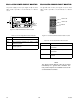
The IDC has three LEDs (located at the center of the
IDC communication module circuit board) to provide
a visual indication of device status.
NOTE
The Initiating Device Circuit Ground Fault Monitor
responds to the presence of a ground fault within
the power circuitry. It provides a supervised dry
contact input and ground fault monitoring
circuitry for indicating a power supply trouble
condition.
NOTE
A blinking red LED on an IDCSC indicates
trouble such as a wiring fault (open or short
circuit) or not congured.
EQ22xxDCU AND EQ22xxDCUEX
DIGITAL COMMUNICATION UNITS
The DCUs have three LEDs to provide a visual
indication of device status. They are visible through
the window on the enclosure cover.
NOTE
If the communication module has not been
congured, the red LED blinks at a 4 Hz rate.
NOTE
The amber LED is provided for factory diagnostic
purposes and is not used in the system.
Illumination of the amber LED normally indicates
a failure in the communication chip.
Replacement of the communication module
circuit board is required.
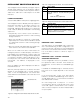
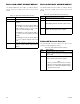
LED Device status
Green When On indicates device has power.
Red When On indicates an Alarm or Fault condition is
present.
On steady = One of the inputs is active.
Blinking = Fault condition such as an open
input circuit or not congured.
Amber When On indicates a device is disabled. Module must
be replaced.
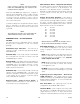
Table 4-16—Initiating Device Circuit Status Indicators
Device Status LED Status
Power-up Pulsed at a rate of 0.5 Hz
Calibration Pulsed at a rate of 1 Hz or on
steady
Fault Pulsed at a rate of 4 Hz
Alarm On steady
Table 4-17—DCU Status Indicators