
Manual

14.1 95-85334-8
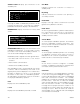
8. ControlNet communication continues.
9. Text display’s first line indicates "*** Program
Mode ***"
10. Text display’s third line displays download status.
a) "Config Download" indicates the serial transfer
into memory from the PC to the Controller.
b) "Erasing Flash" indicates that the controller is
electronically erasing the contents of the Flash
memory.
c) "Writing to Flash" indicates that configuration
data stored in memory is being written down
into Flash memory.
d) "Flash Lock" indicates that the controller is
locking the configuration data into the Flash
memory.
Caution
The controller’s configuration data will be
corrupted if power is removed during a
download. Contact the factory if this occurs.
11. Initialize the RS-485 and configuration serial ports
with new parameters.
12. Initialized the ControlNet option board with new
parameters.
13. Enable static logic and user logic programs to
operate. The first scan program is run first.
14. Accept field device LON communications.
15. Poll the device type variable from LON field
devices.
16. Configure LON field devices.
17. Clear the Trouble condition.
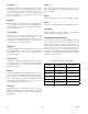
18. Text display shows a normal operation marquee
message.
a) Text display’s first line indicates "Det-Tronics
Eagle Quantum Premier".
b) Text display’s third line displays time (24 hour
format) and date (month day/year).
NOTE
Depending on the condition of the LON devices,
faults may persist for a number of minutes.
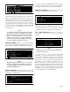
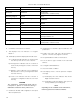
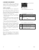
A and B Cause Action
Off No power None or power up.
Steady red Faulted unit Cycle power.
If fault persists, contact the factory.
Alternating red/green Self-test None
Alternating red/off Incorrect node conguration Check network address and other ControlNet conguration
parameters.
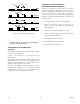
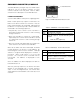
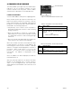
A or B Cause Action
Off Channel disabled Program network for redundant media, if required.
Steady green Normal operation None
Flashing green/off Temporary errors None; unit will self-correct.
Listen only Cycle power.
Flashing red/off Media fault Check media for broken cables, loose connectors,
missing terminators, etc.
No other nodes present on network Add other nodes to the network.
Flashing red/green Incorrect network conguration Cycle power or reset unit.
If fault persists, contact the factory.
Table 4-3—Status of ControlNet LED Indicators