
Manual

14.1 95-85334-2
CONTROLLER STATUS INDICATORS
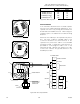
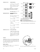
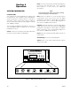
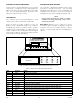
System status is visually displayed on the Controller
in two ways — through the use of a Text Display (see
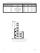
Figure 4-2), and through colored LED’s (see Table
4-1). The following paragraphs describe these
indicators and the function of each.
TEXT DISPLAY
The Controller uses a text based display to show
current system status, active Alarms and Faults.
When an alarm or trouble condition occurs, the
display scrolls a detailed message of the condition,
including tag number, condition (alarm, trouble,
supervisory etc.) and time/date. If multiple alarms or
trouble conditions exist, the display scrolls through all
active status conditions until they go inactive and are
reset using the controller pushbutton.
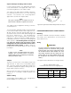
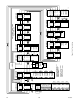
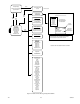
CONTROLLER MENU OPTIONS
The Controller is designed to display system status
and device related information. The following
paragraphs describe how to move around within the
controller’s menu structure to access this information
and perform minor system settings (see Figure 4-3).
NOTE
During normal operation (no alarms or trouble
conditions occurring), the display scrolls current
system time and date.
Main Menu displays a list of options to access
information types available for display through the
Controller. This list also includes access to options
used to set system date and time, and diagnostics
options.
LED Function Status
Green Power On when power is applied.
Red Fire Alarm On (latched) when any re alarm is active (Fire detected).
Amber Trouble On (latched) when a fault is detected in the system. (Indicates "Trouble" relay state.)
Amber Ack On when the Acknowledge button is pressed.
Amber Silence On when Silence pushbutton is pressed.
Amber Inhibit On when any input channel is inhibited.
Amber Out Inhibit On when any output is inhibited.
Red High Gas On (latched) when any gas detector is at or above the High gas alarm value.
Red Low Gas On (latched) when any gas detector is at or above the Low gas alarm value.
Amber Supr On (latched) when any Supervisory input is active.
Amber LON Fault On when a LON fault is detected (open or short).
Amber Contrl Fault On when a processor fault occurs.
Fire Alarm Inhibit Power
SuprHigh Gas
Trouble
Cntrl Flt
Lon FaultLow Gas Ack Silence
Out Inhibit
Eagle Quantum Premier
Time & Date
EAGLE QUANTUM PREMIER
Safety System Controller
Fire Alarm Inhibit Pow er
SuprHigh Gas
Trouble
Cntrl Flt
Lon FaultLow Gas Ack Silence
Out Inhibit
Eagle Quantum Premier
Time & Date
Cancel Enter Next Previous Reset Acknowledge Silence
DET-TRONICS
®
Table 4-1—EQP Controller LED System Status Indicators
Figure 4-2—EQP Controller Message Display and System Status Indicator Location