
Manual

14.1 3-46 95-8533
GAS DETECTOR LOCATION AND
INSTALLATION
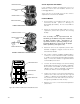
Gas detection devices must be properly located to
provide maximum protection. Determining the proper
number of devices and placement varies depending
on the specific requirements of the area of protection.
The following should be considered when locating a
gas detection device:
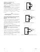
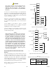
1. Gas type. If it is lighter than air (acetylene,
hydrogen, methane, etc.), place the sensor above
the potential source. Place the sensor close to
the floor for gases that are heavier than air
(benzene, butane, butylene, propane, hexane,
pentane, etc.) or for vapors resulting from
flammable liquid spills.
NOTE
Air currents can cause a gas that is heavier than
air to rise. Also, if the gas is hotter than ambient
air, it could also rise.
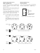
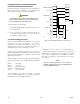
2. How rapidly will the gas diffuse into the air?
Select a location for the sensor as close as
possible to the anticipated source of a gas leak.
3. Ventilation characteristics. Air movement will
cause gas to accumulate more heavily in one area
than another. The devices should be placed in
areas where the most concentrated accumulation
of gas is anticipated.
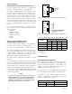
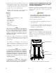
4. Devices should be pointed down to prevent the
buildup of moisture or contaminants on the filter.
5. Devices must be accessible for testing and
calibration.
NOTE
The use of the Sensor Separation Kit will be
required in some installations.
ENVIRONMENTS AND SUBSTANCES THAT
AFFECT GAS DETECTOR PERFORMANCE
Catalytic sensors should be located where they are
safe from potential sources of contamination that can
cause a decrease in the sensitivity of the device
including:
A. Substances that can clog the pores of the flame
arrestor and reduce the gas diffusion rate to the
sensor including:
Dirt and oil, corrosive substances such as Cl
2
(Chlorine) or HCl, paint overspray, or residue from
cleaning solutions that can clog the flame arrestor.
NOTE
A dust cover should be installed to protect the
ame arrester whenever these conditions exist.
B. Substances that cover or tie up the active sites on
the catalytic surface of the active sensing element
such as volatile metal organics, gases, or vapors
of hydrides, and volatile compounds containing
phosphorous, boron, silicone, etc.
Examples:
RTV silicone sealants
Silicone oils and greases
Tetraethyl lead
Phosphine
Diborane
Silane
Trimethyl chlorsilane
Hydrogen fluoride
Boron trifluoride
Phosphate esters
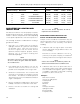
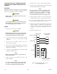
Table 3-16—Maximum Wiring Length for FM Approved Solenoids for Deluge and Pre-Action Applications
Solenoids Maximum Wire Length in Feet (Meters)
FM Solenoid Group Manufacturer Model 12 AWG 14 AWG 16 AWG 18 AWG
B ASCO T8210A107 183 (56) 115 (35) 72 (22) 46 (14)
D ASCO 8210G207 314 (96) 198 (60) 124 (38) 78 (24)
E Skinner 73218BN4UNLVNOC111C2 331 (101) 208 (63) 131 (40) 82 (25)
F Skinner 73212BN4TNLVNOC322C2 130 (40) 82 (25) 51 (16) 32 (10)
G Skinner 71395SN2ENJ1NOH111C2 331 (101) 208 (63) 131 (40) 82 (25)
H Viking HV-274-0601 180 (55) 110 (34) 70 (21) 45(14)