
Manual

14.1 3-38 95-8533
NOTE
In EQP systems with EQP2120PS(–B) Power
Supplies, the secondary power is customer
supplied and must be accepted by the Authority
Having Jurisdiction (AHJ).
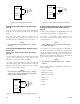
Unsupervised Output Ancillary Applications
(Unrelated to Fire Detection/Protection)
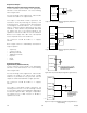
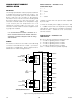
Connect external wiring to the appropriate terminals
on the DCIO terminal block. See Figure 3-44.
NOTE
No connection should be made to the “+ Supply”
terminal.
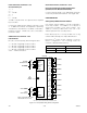
CONFIGURATION
Setting DCIO Network Address
One unique network address must be assigned to
each DCIO module. The address is set by the 8
switch DIP assembly on the DCIO module. The
address is binary coded and is the sum of all
switches placed in the “closed” position.
Each discrete point of a DCIO module has a tag
number and a descriptor for unique identification. A
tag number must include zone designation, which will
be shown on the controller's display when the point is
in alarm.
Det-Tronics S
3
Safety System Software is used for
device configuration. The following shows the
minimum software/firmware releases:
8 CHANNEL RELAY MODULE
INSTALLATION
The following paragraphs describe how to properly
install and configure the 8 Channel Relay Module.
MOUNTING
The Relay Module must be properly installed in a
suitable enclosure that is rated for the location. The
enclosure must provide space to install and wire the
relay module and must also provide for ground wire
termination. Access into the enclosure is gained by
using a special tool to open the enclosure. The
enclosure should be rated for the temperature range
of the location plus the temperature rise of all
equipment installed inside the enclosure. The
enclosure must be rated for electrical equipment that
is going to be installed. The device can be panel or
DIN rail mounted.
NOTE
It is recommended to maintain a minimum of 4
inches clearance between the module and other
equipment to provide adequate room for wiring
and ventilation.
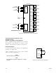
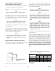
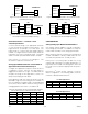
WIRING
All electrical connections are made to the field wiring
connectors furnished with the module. See Figure
3-45 for terminal identification.
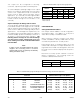
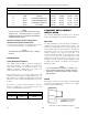
Table 3-13—Maximum Wire Length for FM Approved Solenoids for Deluge and Pre-Action Applications
Solenoids Maximum Wire Length in Feet (Meters)
FM Solenoid Group Manufacturer Model 12 AWG 14 AWG 16 AWG 18 AWG
B ASCO T8210A107 183 (56) 115 (35) 72 (22) 46 (14)
D ASCO 8210G207 314 (96) 198 (60) 124 (38) 78 (24)
E Skinner 73218BN4UNLVNOC111C2 331 (101) 208 (63) 131 (40) 82 (25)
F Skinner 73212BN4TNLVNOC322C2 130 (40) 82 (25) 51 (16) 32 (10)
G Skinner 71395SN2ENJ1NOH111C2 331 (101) 208 (63) 131 (40) 82 (25)
H Viking HV-274-0601 180 (55) 110 (34) 70 (21) 45(14)
Figure 3-44—Unsupervised Output Conguration
+ SUPPLY A
IN– / OUT+ B
COMMON C
1
2
3
NOTE: SHUNT/FLYBACK DIODES DO NOT NEED
TO BE INSTALLED ON THE FIELD DEVICE.
CIRCUIT PROTECTION IS PROVIDED
WITHIN THE DCIO.
A2323
Controller Firmware S3
Revision Version Version
A 1.03 2.0.2.0