
Manual

14.1 3-24 95-8533
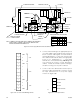
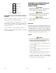
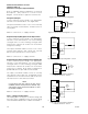
4. Connect external wiring to the appropriate points
on Power Supply. Refer to Figure 3-18 for terminal
block locations and Figures 3-19 and 3-20 for
terminal identification.
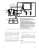
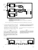
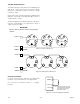
Connect the 24 vdc power
wires and the LON network cable to the appropriate
points on J1. (Redundant “+”, “–” and shield
terminals are connected internally.) Do not ground
any shield at the monitor / power distribution
cabinet. Insulate the shields to prevent shorting to
the device housing or to any other conductor.
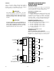
5. Connect a two wire cable between the AC input of
the power supply and terminals 1 and 4 on J3, the
AC input terminal block on the power supply
monitor. See Figure 3-20.
+
J1: POWER AND LON WIRING LON ADDRESS SWITCHES J3: AC INPUT
TERMINAL NO. 1
YELLOW LED
RED LED
GREEN LED
TERMINAL NO. 1
TERMINAL "B"
TERMINAL "C"
J2: BATTERY TEST POINTS
TERMINAL NO. 1
SWITCH NO. 1
1
1
12
3
4
1
C1949
ALARM LEVEL 1 2 3 4
200 mA O O – –
400 mA X O – –
800 mA O X – –
2 AMP X X – –
X = CLOSED
O = OPEN
ALARM CURRENT LEVEL SWITCH SETTINGS
TERMINAL J2-1 TO
TERMINAL B
TERMINAL J2-2 TO
TERMINAL C
POWER SUPPLY MONITOR
PC BOARD ASSEMBLY
J2
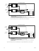
NOTE: J2 TERMINALS 3 AND 4 ARE CONNECTED TO J1 TERMINALS 7 AND 8 INTERNALLY
ON THE PC BOARD. J1 TERMINALS 7 AND 8 ARE ALSO CONNECTED TO THE
BATTERY CIRCUIT BREAKER VIA POWER DIST CKT.
+
–
0.0005 OHM SHUNT
Figure 3-18—Power Supply Monitor Terminal and Switch Location
1
2
3
4
5
6
7
8
9
10
A1947
11
12
SHIELD
SHIELD
SHIELD
SHIELD
A
B
A
B
–
+
–
+
COM 2
24 VDC
COM 1
Figure 3-19—J1: Power and LON Wiring Terminal
A1950
1
2
3
4
AC INPUT 120 / 240 VAC
AC INPUT 120 / 240 VAC
NOT USED
NOT USED
Figure 3-20—J3: AC Input Terminal