
Manual

3-1914.1 95-8533
Use Port 2 to pass safety critical information between
controllers. User logic can pass all alarm, trouble,
and supervisory information between the controllers.
Watchdog timers must be implemented in user logic
to verify the integrity of the SLC. Consult the local
authority having jurisdiction for annunciation
requirements.
CONTROLLER TO CONTROLLER COMMUNICATION
Controller to Controller Communication (SLC485)
with Signaling Line Circuit Classication
Class B or X, per NFPA 72
To connect up to twelve controllers together and be
able to transfer safety information between the
controllers, the communication link must be classified
as a signaling line circuit per NFPA 72. With the serial
board option, Port 2 (plug 10) is a RS-485 serial
connection that is ground fault monitored.
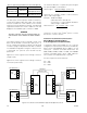
To meet the signaling line circuit (Class B or Class X)
requirements, the following must be configured for
correct operation:
•Allcontrollersmusthavetheoptionalserialboard.
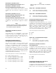
•The Termination jumper P28 must be set to
Terminate (position 1-2) on all controllers.
•TheGroundFaultMonitorjumperP29mustbesetto
Enabled (position 1-2) on all controllers.
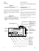
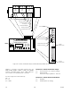
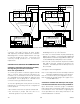
•For Class X, Connect terminals A (# 56) and B (# 55)
betweenthecontrollers.ConnectterminalA(#60)and
B(#61)betweencontrollersusingadifferentcableroute.
ConnectGND(#54)toGND(#62)oneachcontroller.
•For Class B, connect terminals A (terminal number
60) and B (terminal number 61) between the
controllers. The GND (terminal number 62) must not
be connected.
See Figure 3-13 for wiring details.
Note 1: 56.7 kbps minimum and 115.2 kbps maximum
baud rate required for proper communication.
Note 2: Consult the factory for configuration set-up.
Note 3: Maximum SLC485 length over copper not to
exceed 1000 meters.
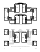
Controller to Controller with Fiber Optic Link, Signal
Line Circuit Classication Class B or X per NFPA 72.
Up to twelve EQP controllers (single or redundant
pair) can be inter-connected via a fiber optic link. This
communication link is classified as a signaling line
circuit per NFPA 72 to allow safety information to be
transferred between controllers.
6062 61
61
6365 6467
6467
6668
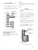
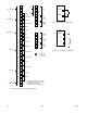
P28: RS-485 Termination Jumper,
Position 1 & 2
P29: RS-485 Ground Fault
Monitor Jumper, Position 1 & 2
A B
P28
1
3
P29
1
3
P12
PORT 4
P11
PORT 3
P10
PORT 2
606263656668
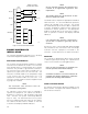
P28: RS-485 Termination Jumper,
Position 1 & 2
P29: RS-
485 Ground Fault
Monitor Jumper, Position 1 & 2
A B
P28
1
3
P29
1
3
P12
PORT 4
P11
PORT 3
P10
PORT 2
GND AB
GND AB
D2276
TO
ADDITIONAL
CONTROLLER(S)
54
55
56
54
55
56
EAGLE QUANTUM PREMIER
Safety System Controller
Fire Alarm Inhibit Po wer
SuprHigh Gas
Trouble
Cntrl Flt
Lon Fault
Low Gas
Ack Silence
Out Inhibit
Eagle Quantum Premier
Time & Date
Cancel Enter Next Previous Reset Acknowledge Silence
DET-TRONICS
®
EAGLE QUANTUM PREMIER
Safety System Controller
Fire Alarm Inhibit Po wer
SuprHigh Gas
Trouble
Cntrl Flt
Lon Fault
Low Gas
Ack Silence
Out Inhibit
Eagle Quantum Premier
Time & Date
Cancel Enter Next Previous Reset Acknowledge Silence
DET-TRONICS
®
Figure 3-13—Controller to Controller Communication with Class A Signaling Line Circuit Classication per NFPA 72