Instructions 95-8533 Eagle Quantum Premier® Fire and Gas Detection/Releasing System 14.
Table of Contents Section 1 - Safety Section 3 - Installation Alert Messages...............................................................1-1 Safety system Design Requirements..................... 3-1 Identifying the Area of Protection................................... 3-1 Section 2 - Introduction Identifying Wiring, Network (LON), and System Power Requirements......................................................... 3-1 SYSTEM DESCRIPTION.......................................................
Table of Contents – Continued EQ3XXX Controller Installation........................... 3-14 analog input module installation........................ 3-40 Enclosure Requirements.............................................. 3-14 Mounting...................................................................... 3-40 Mounting...................................................................... 3-14 Wiring...........................................................................
Table of Contents – Continued Section 4 - Operation EQ21xxPSM POWER SUPPLY MONITOR........................ 4-18 System Controller....................................................... 4-1 eq2220GFM ground fault monitor......................... 4-18 Pushbuttons................................................................... 4-1 Controller Status Indicators............................................ 4-2 EQ22xxIDC series Initiating Device Circuit......... 4-19 Controller Menu Options................
Table of Contents – Continued Section 5 - Maintenance Routine Maintenance................................................... 5-1 Batteries......................................................................... 5-1 Manual Check of Output Devices................................... 5-1 O-Ring Maintenance...................................................... 5-1 GAS SENSOR MAINTENANCE............................................ 5-1 Calibration and Adjustments...................................
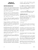
Instructions Eagle Quantum Premier® Fire and Gas Detection/ Releasing System Section 1 Safety Alert Messages The following Alert Messages, DANGER, WARNING, CAUTION, and IMPORTANT are used throughout this manual and on the system to alert the reader and operator to dangerous conditions and/or important operational or maintenance information. DANGER! Identifies immediate hazards that WILL result in severe personal injury or death.
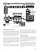
Section 2 Introduction instruments. Typical output equipment includes solenoids, strobes, and horns. All equipment is monitored for wiring fault conditions. For complete system integration, the Controller has the capability to communicate with other systems such as PLCs and DCSs. Different communication protocols are supported, allowing the Controller to communicate with other systems either directly or through communication gateways.
GAS DETECTION CONFIGURABLE INPUTS AND OUTPUTS FIRE DETECTION COMBUSTIBLE, TOXIC, POINTWATCH OR OTHER 4-20 MA INPUT CONTACT CLOSURE DEVICES DIGITAL COMMUNICATION UNITS X3301 DETECTOR X3302 DETECTOR UVHT/C7050 DETECTOR UV DETECTOR UV/IR DETECTOR IR DETECTOR DRY CONTACT INPUTS INITIATING DEVICE CIRCUIT CONFIGURABLE OUTPUT POINTS 8 CHANNEL DCIO MODULE NOTE: CHANNELS CAN BE CONFIGURED AS EITHER INPUTS OR OUTPUTS.
Table 2-1—Controller Based Faults Controller Faults Trouble Shown on Text Display LED Table 2-2—Field Device Based Faults LON Fault Trouble LED Relay Field Device Faults Trouble Trouble Shown on Text Display LED Relay Controller Fault X X 290 Volt Fault X X Device Offline X X AC Failed X X Extra LON Device X X Battery Fault X X Invalid Config X X Beam Block X X Lon Fault X X X Calibration Fault X X LON Ground Fault X X Channel Open X X Power Fail 1 X
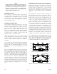
COMMUNICATION NETWORK FAULT OPERATION Note All fault and alarm conditions are latched on the Controller. To reset the Controller, conditions indicated on the text display must currently be in the OFF state. Pushing the reset button then initiates a Controller reset. Active alarms will remain through a Controller reset. During normal operation, the Controller is continuously broadcasting a heartbeat around the communication loop as shown in Figure 2-2.
NODE 4 NODE 5 NODE 3 NODE 2 • 8 programmable unsupervised relay outputs WIRING FAULTS NODE 7 • RS-485 Modbus RTU communication interface that supports coils, discrete inputs, and holding registers NODE 8 • Optional ControlNet communication board that supports redundant communication channels.
During normal operation one controller acts as the “Master” while the other acts as the “Hot Standby”. Controller-to-Controller Communication (SLC485) The EQP controllers can be configured to communicate with up to 12 controllers via RS-485 communication. The controller-to-controller scheme provides the ability to meet NFPA 72 SLC requirements with the following primary features: Terminology used for redundancy: This is the normal mode for non-redundant and master controllers.
EQP21XXPS(–X) Power Supplies and EQP2410PS(–P) Converter The Power Supplies and Converter provide main and backup power to the EQP System in ordinary and marine applications. Refer to Section 3 of this manual for complete information. EQ2220GFM Ground Fault Monitor The EQ2220GFM Ground Fault Monitor (see Figure 2-8) provides ground fault monitoring in a system that includes a floating 24 Vdc power source. The device detects ground fault conditions on +/– power and all secondary I/O circuits.
EQ3730EDIO Enhanced Discrete Input/Output Module EQ3700 8 Channel DCIO Module The 8 Channel EDIO Module (see Figure 2-9) expands the Input and Output capability of the Eagle Quantum Premier System. The 8 Channel Discrete Input/Output (DCIO) Module (see Figure 2-10) consists of eight individually configured channels. Each channel is configured as either an input or output with the appropriate wiring supervision. Wiring supervision includes none, open circuits, and "open and short" circuits.
EQ3720 8 Channel Relay Module EQ3710AIM Analog Input Module The 8 Channel Relay Module (see Figure 2-11) consists of eight individually configured output channels. The 8 Channel Analog Input Module (see Figure 2-12) provides a means of connecting devices with a calibrated 4-20 mA output signal to the Eagle Quantum Premier System. Note The relay module only supports equipment that operates on 24 vdc (not to exceed 2 amperes) at each output channel.
EQ3740IPM Intelligent Protection Module EQ3750ASH Addressable Smoke & Heat Module The IPM (see Figure 2-13) is designed to provide continuous and automated local area fire protection, while monitoring system operation through continuous supervision of its Inputs/Outputs and Local Operating Network/Signalling Line Circuit (LON/SLC) connection to the EQP controller.
The device can monitor and control two output devices (24 vdc rated) that are programmed and energized together. The release circuits are compatible with a variety of solenoid or initiator based suppression systems. EQ25xxARM Agent Release Module The EQ25xxARM Series Agent Release Module (ARM) (see Figure 2-15) provides agent release or deluge pre-action capability. The device is controlled by programmable logic in the Controller.
EQ25xxSAM Signal Audible Module EQ22xxIDC Series Initiating Device Circuit (IDC) The EQ25xxSAM Series Signal Audible Module (SAM) (see Figure 2-16) provides two indicating circuits for controlling UL Listed 24 vdc polarized audible/visual indicating appliances. There are three IDC models available (see Figure 2-17): The EQ22xxIDC allows discrete inputs from smoke/ heat detectors, manual call stations or other contact devices.
EQ22xxDCU and EQ22xxDCUEX Digital Communication Units PIRECL PointWatch Eclipse The Pointwatch Eclipse® Model PIRECL is a diffusionbased, point-type infrared gas detector that provides continuous monitoring of combustible hydrocarbon gas concentrations in the range of 0 to 100% LFL. The EQ22xxDCU Digital Communication Unit (DCU) is an analog signal input device that accepts a 4 to 20 milliampere signal.
Section 3 Installation CAUTION! A ny d ev i a t i o n f ro m t h e m a n u fa c t u re r ’s recommended wiring practices can compromise system operation and effectiveness. ALWAYS consult the factory if different wire types or methods are being considered. NOTE For specific information regarding systems meeting EN54 standards, refer to the EQ5400 Series operation manual 95-8642. Note All field wiring must be marked per NFPA 70 Article 760.
The EQP Ex n modules may only be installed, connected or removed when the area is known to be non-hazardous. The screw terminals are to be tightened with a minimum torque of 0.5 Nm. Equipotential bonding connection facilities on the outside of electrical equipment shall provide effective connection of a conductor with a cross-sectional area of at least 4 mm2.
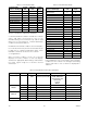
Determining Power Requirements Tables 3-1 and 3-2 are provided for calculating the total current requirements for those parts of the system requiring battery backup. Table 3–1—Standby Current Requirements at 24 vdc Device Type Number of Devices Standby Current Total Current for Device Type EQP Controller X 0.360 = EQ3LTM Module X 0.001 = EDIO Module X 0.075 = DCIO Module X 0.075 = Power Supply. Monitor X 0.060 = IDC/IDCGF/IDCSC X 0.055 = X3301/X3301A - w/o heater X 0.
Table 3-2—Alarm Current Requirements at 24 Vdc Device Type Number of Devices Alarm Current Total Current for Device Type EQP Controller X 0.430 = EQ3LTM Module X 0.001 = EDIO 8 Inputs X 0.130 = EDIO 8 Outputs X 0.075 = DCIO 8 Inputs X 0.130 = DCIO 8 Outputs X 0.075 = Relay Module X 0.120 = Power Supply Monitor X 0.060 = IDC/IDCGF/IDCSC X 0.090 = X3301/X3301A - w/o heater X 0.160 = X3301/X3301A - with heater X 0.565 = X3302 - without heater X 0.
Table 3-3A—EQ21xxPS Power Supply Specifications Characteristic Power Supply EQ2110PS/EQ2111PS EQ2130PS/EQ2131PS EQ2175PS/EQ2176PS Input Voltage 120 vac 120/208/240 vac 120/208/240 vac Input Current 4 Amps 11/6/6 Amps 24/15/12 Amps Input Frequency 60 Hz – EQ2110PS 60 Hz – EQ2130PS 60 Hz – EQ2175PS Input Frequency 50 Hz – EQ2111PS 50 Hz – EQ2131PS 50 Hz – EQ2176PS Supply Rating 10 Amps 30 Amps 75 Amps Maximum Alarm Current 10 Amps 30 Amps 75 Amps Maximum Standby Current 3.
Table 3-4—Backup Battery Requirements for Automatic Release of Extinguishing Systems Except Deluge Standby Current Alarm Current X X Standby Time* 24 Hours 5 Minute Alarm Time* 0.083 Hours = = Sum of Standby and Alarm Amp Hours = Multiply by 1.2 (20% Safety Factor) X Standby Amp Hours Alarm Amp Hours T0014B Total Battery Amp Hour Requirement * FM MINIMUM REQUIREMENT FOR EXTINGUISHING SYSTEMS IS 24 HOURS STANDBY TIME AND 5 MINUTES ALARM TIME.
Table 3-3B – EQP2XX0PS Power Supply and Converter Specifications Device Characteristic EQP2110PS(-P) Power Supply EQP2120PS(-B) Power Supply EQP2410PS(-P) Converter Input Frequency 60/50 60/50 N/A Input Voltage 120/220 Vac 120/220 Vac 24 Vdc Input Current, Max. 3.2 / 1.7 Iac 6.6 / 3.6 Iac 15.7 Idc Output Voltage Range 24.5 … 28.0 Vdc 24.5 … 28.0 Vdc 24.5 … 28.
Shield Grounding caution! Two shield ground terminals are provided inside the junction box of each device, and also at the System Controller. Connect shield ends to the terminals provided (not to each other) inside the junction box. ALWAYS discharge static charges from hands before handling electronic devices or touching device terminals. Many devices contain semiconductors that are susceptible to damage by electrostatic discharge.
NETWORK AND NETWORK EXTENDER INSTALLATION Table 3-7—LON Maximum Cable Lengths Mounting The device should be securely mounted to a vibration free surface. (See the “Specifications” section in this manual for device dimensions.) LON Cable Maximum Length** (Manufacturer and Part No.
Table 3-8—Maximum Wiring Length from Nominal 24 vdc Power Source to Network Extender (Maximum wire lengths are based upon the cable’s physical and electrical characteristics.) IMPORTANT! Det-Tronics recommends the use of shielded cable (required by ATEX) to prevent external electromagnetic interference from affecting field devices. Wire Size 18 AWG (1.0 mm2)* 16 AWG (1.5 mm2)* 14 AWG (2.5 mm2)* IMPORTANT! 2. Connect 24 vdc power lead wires and communication network cable to the terminal block.
1 SHIELD 2 A 3 B 4 SHIELD 5 + 6 – 7 – 8 + 9 SHIELD 10 A 11 B 12 SHIELD COM 1 GND 11 12 1 2 3 4 5 6 7 8 9 14 10 13 24 VDC A1870 Figure 3-4—IDC Terminal Wiring Board Mounted in Six-Port Junction Box COM 2 Wiring A1947 Figure 3-3—Network Extender Wiring Terminal Identification INITIATING DEVICE CIRCUIT (IDC) INSTALLATION 1. Remove the cover from the device junction box. 2. Connect external system wiring to the appropriate terminals on the terminal block.
Mounting Note The recommended lubricant is a silicone free grease, available from Det-Tronics. The device should be securely mounted to a vibration free surface. (See “Specifications” in this manual for device dimensions.) 6. Set the node address for the device. (See “Setting Device Network Addresses” in this section.) Wiring 7. Place the cover on the junction box and tighten only until snug. DO NOT over tighten. WARNING! The enclosure must be electrically connected to earth ground.
WARNING! Wiring If the installation uses catalytic type combustible gas sensors, it is imperative that lubricants containing silicone not be used, since they will cause irreversible damage to the sensor. 5. Install the communication module in the device enclosure. Note Be sure the ribbon cable is properly connected. 6. Set the node address for the device.
Note For any selected enclosure, the enclosure must conform to all applicable regulations and requirements. MANUAL PULL STATION OR OTHER CONTACT DEVICE IDCSC + 1 – 2 + 3 – 4 A 5 B 6 EOL (10K) CIRCUIT 1 3.3 K NOTE The Trouble signal must be located in an area where it is likely to be heard. EOL (10K) CIRCUIT 2 3.3 K Classified locations require the appropriate hazardous rated enclosure. It is recommended that operators/ switches be installed in the enclosure.
WIRING Electrical Connections Figure 3-8 shows the location of wiring connectors on the Controller module. Figure 3-9 identifies individual terminals. Power Wiring caution! Connector P1, Terminals 1 to 4 — 24 vdc Input Power Input voltage at the Controller must be 18 vdc minimum to ensure proper operation. Connect the power supply to terminals 1 and 2 of the Controller. Terminals 3 and 4 must also be connected to power.
P1 24 VDC INPUT POWER P2 DIGITAL INPUTS 1 TO 4 P3 DIGITAL INPUTS 5 TO 8 P4 RELAYS 1 TO 4 P5 RELAYS 5 TO 8 P6 TROUBLE RELAY + 1 48 SHIELD 49 1B – 2 + 3 50 1A – 4 51 SHIELD 1+ 5 52 2B 1– 6 2+ 7 COM 1 RESET* COM 2 ACKNOWLEDGE* 53 2A 54 GND 55 B 2– 8 3+ 9 3– 10 4+ 11 4– 12 5+ 13 5– 14 6+ 15 6– 16 7+ 17 7– 18 8+ 19 8– 20 1 C 21 1 NO 22 1 NC 23 2 C 24 67 RxD 2 NO 25 68 GND 2 NC 26 3 C 27 3 NO 28 3 NC 29 4 C 30 4 NO 31 4 NC
Connector P2, Terminals 5 to12 — Unsupervised Digital Input Channels 1 to 4 NOTE Refer to Figure 3-12 for location of termination jumpers. Connector P3, Terminals 13 to 20 — Unsupervised Digital Input Channels 5 to 8 See Figure 3-10 for example. Only channel 1 is shown in Figure 3-10. The information is typical for channels 2-8.
68 67 66 65 64 63 62 61 P12 P11 P10 PORT 4 PORT 3 PORT 2 60 3 3 P29 P28 1 1 RS-232 Transmit LED (Amber) RS-232 Receive LED (Green) P29: RS-485 Ground Fault MonitorJumper RS-485 Transmit LED (Amber) RS-232 Transmit LED (Amber) RS-485 Receive LED (Green) P28: RS-485 Termination Jumper RS-232 Receive LED (Green) DET-TRONICS A Channel Indicators B ® RS-485 Transmit LED (Amber) EAGLE QUANTUM PREMIER Safety System Controller Eagle Quantum Premier Fire Alarm Time & Date Cancel Ent
TO ADDITIONAL CONTROLLER(S) 68 67 66 65 64 63 62 GND 61 60 B 68 67 66 65 61 62 A GND 60 B A P12 P11 P10 P12 P11 P10 PORT 3 PORT 2 PORT 4 PORT 3 PORT 2 3 3 3 3 P29 P28 P29 P28 1 1 1 P29: RS-485 Ground Fault Monitor Jumper, Position 1 & 2 P29: RS-485 Ground Fault Monitor Jumper, Position 1 & 2 P28: RS-485 Termination Jumper, Position 1 & 2 DET-TRONICS B 63 PORT 4 1 A 64 Fire Alarm Time & Date Cancel Enter Next Previous 56 55 54 Trouble Inhibit High
The maximum distance of a particular optic link given the optical budget is calculated as: Table 3-9—Approved Supported Media Converters for Fiber Optic Link Manufacturer Model Number Description Moxa (www.moxa.com) TCF-142-S RS-485 to Single-mode Fiber Optical Converter Phoenix Contact PSI-MOSRS485W2/FO RS-485 to Multi-mode Fiber Optical Converter Fiber Length = [Optical budget] – [Link Loss] [Fiber Loss / km] where link loss includes number of end connectors, splices and safety margin.
SINGLE MODE FIBER OPTIC CABLE Rx Tx Tx Rx T+ T+ T– EQP CONTROLLER No. 1 T– R+D+ R–D– PORT 2 RS-485 Moxa TCF-142-S Moxa TCF-142-S R+D+ EQP CONTROLLER No.
Connector P12, Terminals 66, 67 & 68, Port 4– RS-232 Modbus RTU Master/Slave (Non-Isolated) EQP CONTROLLER Configuration data downloaded into the controller configures the serial interface transmission baud rate, parity check and MODBUS device address for the serial port. Software selectable baud rates are 9600,19200, 38400, 57600, 115200, and 230400. Software selectable parity is None, Odd, and Even. The controller uses 8 data bits with 1 stop bit.
CONFIGURATION IMPORTANT! S3 Configuration The S3 configuration software is used to configure the redundant controllers. A check box on the controller configuration screen must be enabled and downloaded to the controllers. IMPORTANT If the controllers have not been configured for redundancy via the S3 configuration software, redundancy will not function. Power supplies require unrestricted air flow for proper cooling.
J1: POWER AND LON WIRING LON ADDRESS SWITCHES J3: AC INPUT TERMINAL NO. 1 1 TERMINAL J2-1 TO TERMINAL B 1 TERMINAL J2-2 TO TERMINAL C J2 SWITCH NO. 1 + – 4 3 2 1 + 1 YELLOW LED RED LED TERMINAL NO. 1 GREEN LED C1949 0.0005 OHM SHUNT J2: BATTERY TEST POINTS TERMINAL NO. 1 ALARM CURRENT LEVEL SWITCH SETTINGS TERMINAL "C" POWER SUPPLY MONITOR PC BOARD ASSEMBLY TERMINAL "B" NOTE: J2 TERMINALS 3 AND 4 ARE CONNECTED TO J1 TERMINALS 7 AND 8 INTERNALLY ON THE PC BOARD.
POWER SUPPLY MONITOR See Note 10 1 AC MONITOR 4 C B AC POWER H See Notes 1 & 3 N – – + + 12 11 10 9 8 7 6 5 4 3 2 1 TERMINAL J1 See Note 4 24 VDC OUTPUT G + POWER DIST CKT #1 – + POWER DIST CKT #2 – + POWER DIST CKT #3 – AC BREAKER DC BREAKER + POWER DIST CKT #4 – BATTERY CIRCUIT BREAKER See Note 3 EQ21XXPS POWER SUPPLY (See Note 9) See Note 2 See Note 6 + – 12 VDC E1951 NRTL DISTRIBUTION CABINET + – 12 VDC BACKUP BATTERIES NOTES 1.
1 CURRENT SENSE + 2 CURRENT SENSE – 3 BATTERY – 4 BATTERY + EQP2XX0PS(–X) POWER SUPPLIES AND REDUNDANCY MODULE INSTALLATION WARNING! ALWAYS follow all safety notes and instructions when installing power supply or module! A1952 WARNING! Figure 3-22—J2: Battery Test Points Make sure a.c. power is OFF at main a.c. breaker before beginning power supply installation! MEASURING BATTERY VOLTAGE AND CHARGING CURRENT IMPORTANT! Power supplies require unrestricted air flow for proper cooling.
NRTL DISTRIBUTION CABINET CB AC POWER See Notes 1 & 2 L N G 24 VDC OUTPUT – – + + POWER SUPPLY CB AC POWER See Notes 1 & 2 L N G 24 VDC OUTPUT – – – + + 1 2 IN OUT + + POWER DIST CKT #1 – + POWER DIST CKT #2 – POWER SUPPLY REDUNDANCY MODULE + POWER DIST CKT #3 – + POWER DIST CKT #4 – D2445 NOTES: 1. AC INPUT IS AUTO-SELECTABLE FOR 120–220 VAC, 60/50 Hz (CUSTOMER SUPPLIED). 2.
NRTL DISTRIBUTION CABINET CB AC POWER – L See Notes 1 & 2 24 VDC OUTPUT N – 1 + G OUT IN + EQP2120PS(–X) POWER SUPPLY REDUNDANCY MODULE – – CB DC POWER 24 VDC OUTPUT + See Notes 1 & 2 – – 1 + + 2 + OUT IN + POWER DIST CKT #1 – + + POWER DIST CKT #2 – EQP2410PS(–P) CONVERTER REDUNDANCY MODULE + POWER DIST CKT #3 – + POWER DIST CKT #4 – – 24 VDC OUTPUT + – – + + EQP2410PS(–P) CONVERTER A2566 NOTES: 1. AC INPUT IS AUTO-SELECTABLE FOR 120–220 VAC, 60/50 Hz.
STARTUP Turn on the power supply and allow the voltage to stabilize. Verify the output voltage and adjust as needed. Refer to "EQP2XX0PS(–X) Power Supplies" in the Specifications section of this manual. IMPORTANT! ENHANCED DISCRETE INPUT/ OUTPUT (EDIO) MODULE INSTALLATION All electrical connections are made to the field wiring connectors furnished with the module. Refer to Figure 3-25 for identification of module wiring terminals.
Connector P4, Terminals 13 to 24 Terminals A, B & C Channels 5 to 8 Input / Output Terminals COMMON C 3 Refer to individual wiring configurations for terminal descriptions. Only channel 1 is shown in each diagram. The information is typical for channels 2-8. IN– / OUT+ B 2 + SUPPLY A 1 C2090 Figure 3-26—Unsupervised Input Configuration Unsupervised Input Connect external system wiring to the appropriate terminals on the terminal block. See Figure 3-26.
Two-Wire Smoke Detectors The EDIO supports 2-wire devices from Kidde-Fenwal and Apollo. Figure 3-31 shows the wiring for Apollo detectors connected to EDIO Channel 1 through terminals 1 and 2. Figure 3-32 shows the typical wiring for Kidde-Fenwal detectors connected to the EDIO through Channel 1 using terminals 1 and 2. The EDIO supports either brand of detection products, however, mixing brands is not supported on either a single channel or module.
Supervised Output— Notification Supervised for Open & Short Circuits Connect external system wiring to the appropriate terminals on the terminal block. For Class B wiring, refer to Figure 3-34. COMMON C 3 EOL RESISTOR 10 K Ω IN– / OUT+ B 2 For Class A wiring, refer to Figure 3-35. Note that two channels are used for one output circuit. + SUPPLY A 1 The output of the EDIO module supervises the notification circuit by reversing the polarity of the monitoring circuit.
The output can be configured for latching, continuous, supervisory, trouble or timed response. Table 3-10—Maximum Wire Length for Releasing Applications Maximum Wire Length in Feet Device To ensure adequate operating voltage for the output device, the maximum wiring length from the power source to the output device must not exceed the values shown in Table 3-10 for automatic release applications.
8 CHANNEL DISCRETE INPUT/ OUTPUT (DCIO) MODULE INSTALLATION WIRING All electrical connections are made to the field wiring connectors furnished with the module. See Figure 3-38 for terminal identification. The following paragraphs describe how to properly install and configure the 8 Channel DCIO Module. Power Connector, Terminals 1 to 6 24 Vdc Power Input MOUNTING Power connections to the DCIO depend upon the total current consumption of all the channels in the device.
EQ3700DCIO COMMON C 24 CHANNEL 8 IN–/OUT+ B 23 LON FROM PREVIOUS DEVICE LON TO NEXT DEVICE SHLD 6 COM 2 SHLD B 5 COM 2 B A 4 COM 2 A SHLD 3 COM 1 SHLD B 2 COM 1 B A 1 COM 1 A + SUPPLY A 22 COMMON C 21 CHANNEL 7 IN–/OUT+ B 20 + SUPPLY A 19 COMMON C 18 COM CHANNEL 6 IN–/OUT+ B 17 + SUPPLY A 16 COMMON C 15 CHANNEL 5 IN–/OUT+ B 14 + SUPPLY A 13 TO EARTH GROUND COMMON C 12 CHANNEL 4 IN–/OUT+ B 11 + SUPPLY A 10 COMMON C 9 CHANNEL 3 IN–/OUT+ B 8 24 VDC INPUT VOLTAGE 24 VDC INP
COMMON C 3 COMMON C 3 EOL RESISTOR 10 K Ω EOL RESISTOR 10 K Ω IN– / OUT+ B 2 IN– / OUT+ B 2 + SUPPLY A 1 + SUPPLY A 1 B2091 Figure 3-40—Supervised Input Configuration Figure 3-42—Supervised Output Configuration (Notification) Supervised Input (IDC) Open Circuit Supervision Class B Supervised Output Notification (Horns and Strobes) Supervised Outputs for Open & Short Circuits Class B Connect external system wiring to the appropriate terminals on the DCIO terminal block. See Figure 3-40.
Supervised Output for Automatic Release Supervised Output for Open Circuits Connect external wiring to the appropriate terminals on the DCIO terminal block. See Figure 3-43. The output of the DCIO module supervises the releasing circuit via the coil of the releasing solenoid. It is essential to use a releasing device approved for use with this output module. Note This type of output does not require the use of EOL resistors or diodes to supervise the circuit.
Table 3-13—Maximum Wire Length for FM Approved Solenoids for Deluge and Pre-Action Applications Solenoids Maximum Wire Length in Feet (Meters) FM Solenoid Group Manufacturer Model 12 AWG 14 AWG 16 AWG 18 AWG B ASCO T8210A107 183 (56) 115 (35) 72 (22) 46 (14) D ASCO 8210G207 314 (96) 198 (60) 124 (38) 78 (24) E Skinner 73218BN4UNLVNOC111C2 331 (101) 208 (63) 131 (40) 82 (25) F Skinner 73212BN4TNLVNOC322C2 130 (40) 82 (25) 51 (16) 32 (10) G Skinner 71395SN2ENJ1NOH111C2
Channel Connectors, Terminals 1 to 24 Power Connector, Terminals 1 to 6 24 Vdc Power Input 1— 2— 3— 4— 5— 6— Unsupervised Output Ancillary Applications (Unrelated to Fire Detection/Protection) + – Shield* + – Shield* Connect external wiring to the appropriate terminals on the relay module terminal block. See Figure 3-45. CONFIGURATION *Shields on power wires are optional unless required by local codes. Connect the module power supply to terminals 1 and 2.
ANALOG INPUT MODULE INSTALLATION Power Connector — Terminals 1 to 6 24 Vdc Power Input 1— 2— 3— 4— 5— 6— MOUNTING The Analog Input Module must be properly installed in a suitable enclosure that is rated for the location. The enclosure must provide space to install and wire the device and must also provide for ground wire termination. Access into the enclosure must be gained by using a special tool to open the enclosure.
CHANNEL 1 TRANSMITTER COMMON C 3 4-20 MA IN B 2 SIG + SUPPLY A 1 + A2235 COMMON C 3 – 4-20 MA IN B 2 SIG + SUPPLY A 1 + A2236 Figure 3-47—Two-Wire Transmitter — Non-Isolated 4 to 20 mA Current Output (Sourcing) CHANNEL 1 Figure 3-49—Three-Wire Transmitter — Non-Isolated 4 to 20 mA Current Output (Sourcing) HIM HIM CHANNEL 1 COMMON C 3 6 COMMON 3 4-20 MA IN B 2 5 4-20 MA IN 2 + SUPPLY A 1 4 + SUPPLY TRANSMITTER TRANSMITTER COMMON C 3 6 COMMON SIG 4-20 MA IN B 2 5 4
INTELLIGENT PROTECTION MODULE INSTALLATION LON Connector, Terminals 1 to 6 LON/SLC Signaling Circuit Terminals Be sure to observe polarity when wiring the LON/SLC. WIRING shield connection — terminals 3 and 6. All electrical connections are made to the field wiring connectors furnished with the module. Refer to Figure 3-51 for identification of module wiring terminals.
Channels 1 to 3, Terminals 1 to 9 Channels 1 to 3 Inputs Refer to individual wiring configurations for terminal descriptions. Only channel 1 is shown in each diagram. The information is typical for channels 1-3. COMMON C 3 IN– / OUT+ B 2 Unsupervised Input Connect external system wiring to the appropriate terminals on the terminal block. See Figure 3-52. + SUPPLY A 1 B2090 The input to the IPM consists of one or more normally open switches. An EOL resistor is not required.
Channels 4 and 5, Terminals 10 to 15 ZONE-1 and ZONE-2 Inputs Channel 6, Terminals 16 to 18 Unsupervised Output The IPM supports 2-wire devices from Kidde-Fenwal and Apollo. Figure 3-55 shows the wiring for Apollo detectors connected to IPM Channel 4 through terminals 10 and 11. Connect external system wiring to the appropriate terminals on the terminal block. See Figure 3-57. No connection should be made to “+ Supply” terminal.
Supervised Output Notification Supervised for Open & Short Circuits COMMON C 18 Connect external system wiring to the appropriate terminals on the terminal block. See Figure 3-58. EOL RESISTOR 10 K Ω The output of the IPM supervises the notification circuit by reversing the polarity of the monitoring circuit. Polarity must be observed when connecting the notification device. It is essential to utilize a notification device approved for fire alarm notification.
Table 3-16—Maximum Wiring Length for FM Approved Solenoids for Deluge and Pre-Action Applications Solenoids Maximum Wire Length in Feet (Meters) FM Solenoid Group Manufacturer Model 12 AWG 14 AWG 16 AWG 18 AWG B ASCO T8210A107 183 (56) 115 (35) 72 (22) 46 (14) D ASCO 8210G207 314 (96) 198 (60) 124 (38) 78 (24) E Skinner 73218BN4UNLVNOC111C2 331 (101) 208 (63) 131 (40) 82 (25) F Skinner 73212BN4TNLVNOC322C2 130 (40) 82 (25) 51 (16) 32 (10) G Skinner 71395SN2ENJ1NOH111C
C. Materials that remove the catalytic metals from the active element of the sensor. Some substances react with the catalytic metal forming a volatile compound that can erode the metal from the surface of the sensor’s active element. Halogens and compounds containing halogen are materials of this nature and others include: Examples: Chlorine Bromine Iodine Hydrogen Chloride, Bromide or Iodide Organic halides: Trichloroethylene Dichlorobenzene Vinyl chloride Freons Halon 1301 (Bromotrifluoromethane).
CAUTION! The sensor threads can be coated with an appropriate grease to ease installation. Also lubricate the cover threads. (See “Ordering Information” for part number of recommended lubricant.) POINTWATCH CALIBRATE 1 4 TO 20 MA IN 2 – 3 + 4 A 5 B 6 SENSOR POWER Connect the external wiring to the appropriate terminals on the DCU terminal wiring board. Refer to Figure 3-61 for terminal identification. See Figure 3-62 for an example of a Det-Tronics electrochemical sensor connected to a DCU.
EQ22XXDCU DIGITAL COMMUNICATION UNIT USED WITH POINTWATCH/DUCTWATCH DCU POINTWATCH POINTWATCH CALIBRATE 1 YELLOW 4 TO 20 MA IN 2 WHITE – 3 BLACK + 4 RED A 5 GREEN B 6 Determine the best mounting location for the detector. Whenever practical, detectors should be placed where they are easily accessible for calibration. WARNING! SENSOR POWER Do not apply power to the system with the cover removed unless the area has been verified to be free of combustible gases and vapors.
7. Plug the sensor into P2 on the transmitter board. EQ22XXDCUEX DIGITAL COMMUNICATION UNIT (USED WITH DET-TRONICS COMBUSTIBLE GAS SENSORS) 8. Mount the transmitter board to the terminal wiring board and attach with the standoffs. Mounting NOTE Be sure to note the correct orientation of the transmitter board. If the transmitter board is rotated 180° from proper orientation, the device w i l l n o t o p e r a t e c o r r e c t l y — a LO N communication fault will result. See Figure 3-65.
COMMUNICATION MODULE Sensor Separation with DCUEX SWITCHES ON SAME SIDE (RIGHT) If the installation requires mounting the sensor in a different location than the DCUEX, observe the following guidelines. TRANSMITTER BOARD There are two (2) methods that can be used to separate the sensor from the DCUEX: Preferred Method TERMINAL WIRING BOARD CORRECT ORIENTATION OF TRANSMITTER BOARD 1. Disassemble the DCUEX and remove the transmitter board. (Refer to “Wiring” for disassembly procedure.
Table 3-18—Maximum Separation Distances — Combustible Gas Sensor to DCU (Alternate Method) Wire Size Maximum Separation Distance Feet Meters 18 AWG (1.0 mm2)* 16 AWG (1.5 mm2)* 14 AWG (2.5 mm2)* 12 AWG (4.0 mm2)* 40 60 100 150 12 18 30 45 *Approximate Metric Equivalent. + – Alternate Method N GR If the transmitter board must be mounted separate from the sensor (high temperature applications, etc.), separate the sensor only, leaving the transmitter PC board inside the DCUEX enclosure.
EQ25XXARM SERIES AGENT RELEASE MODULE Terminals 5 to 10 — LO N s i g n a l i n g c i r c u i t terminals Mounting Note Be sure to observe polarity when wiring the LON. The device should be securely mounted to a vibration free surface. (See “Specifications” in this manual for device dimensions.
Table 3-20—Maximum Wiring Length for FM Approved Solenoids for Deluge and Pre-Action Applications Solenoids Maximum Wire Length in Feet (Meters) FM Solenoid Group Manufacturer Model 12 AWG 14 AWG 16 AWG 18 AWG B ASCO T8210A107 183 (56) 115 (35) 72 (22) 46 (14) D ASCO 8210G207 314 (96) 198 (60) 124 (38) 78 (24) E Skinner 73218BN4UNLVNOC111C2 331 (101) 208 (63) 131 (40) 82 (25) F Skinner 73212BN4TNLVNOC322C2 130 (40) 82 (25) 51 (16) 32 (10) G Skinner 71395SN2ENJ1NOH111C
Supervised Output for Deluge and Pre-action Connect external wiring to the appropriate terminals on the terminal block. See Figure 3-67. Wire one or more releasing devices to the module output. JP1 11 12 13 14 The output of the Agent Release Module supervises the releasing circuit via the coil of the releasing solenoid. It is essential to use a releasing device approved for use with this output module.
Terminals 1 to 4 — Output terminals Connect the first output device between terminals 1 and 2, and the second between terminals 3 and 4. + 1 – 2 + 3 – 4 A 5 B 6 OUTPUT 1* 10K EOL OUTPUT 2* Note Polarity shown in Figure 3-69 is for monitoring condition; polarity is reversed when activated. 10K EOL COM 2 Each circuit must have a 10 kohm EOL resistor.
SYSTEM CONFIGURATION ON SETTING DEVICE NETWORK ADDRESSES BINARY VALUE 1 2 3 4 5 6 7 8 1 2 4 8 16 32 64 128 Overview of Network Addresses NODE ADDRESS EQUALS THE ADDED VALUE OF ALL CLOSED ROCKER SWITCHES Each device on the LON must be assigned a unique address. Addresses 1 to 4 are reserved for the controller. Valid addresses for field devices are from 5 to 250. IMPORTANT If the address is set to zero or an address above 250, the communication module will ignore the switch setting.
14.1 C 45 3-58 9 3+ RELAY 1 RELAY 2 RELAY 3 C 42 NO 43 NC 44 31 NO 32 NC RELAY 7 30 C NC 41 29 NC NC 38 26 NC C 39 NO 37 25 NO RELAY 6 NO 40 C 36 24 C RELAY 5 28 NO NC 35 23 NC – 24 VDC BATTERY + H N AC LINE THE DEVICE’S CHASSIS GROUND TERMINAL SHOULD BE CONNECTED TO EARTH GROUND. VALID FOR AIM, IPM, RM, EDIO. SEE INDIVIDUAL DEVICE FOR CHANNEL TERMINALS.
Section 4 Operation Enter chooses the menu item selected, and advances the menu to the next options list. (See “Controller Menu Options“ in this section for additional information.) SYSTEM CONTROLLER Note Pressing Enter while alarms are actively scrolling returns the display to the Main Menu. PUSHBUTTONS The Controller has seven pushbuttons (located on the front panel) for user interface.
CONTROLLER STATUS INDICATORS CONTROLLER MENU OPTIONS System status is visually displayed on the Controller in two ways — through the use of a Text Display (see Figure 4-2), and through colored LED’s (see Table 4-1). The following paragraphs describe these indicators and the function of each. The Controller is designed to display system status and device related information.
Marque Display Alarm Display Current Time/Date (no active alarms) Cancel Reset Enter Next Prev Enter Next Prev Enter / Cancel Display Alarms Display Devices* Device Tagname Add: xxx Device Type Fault/ No Fault Device dependent info Main Menu Next Previous Display Alarms Display Devices Device Tagnames Set Time & Date Serial Ports Diagnostics Redundancy Info Auto Scrolling Alarm Screen Display Alarms Screen Alarm Types Fire Supervisory Trouble Low Gas High Gas Inhibit Output Inhibit Pressing the
Pressing the NEXT or PREVIOUS pushbuttons allows cycling through devices. Pressing the CANCEL pushbutton will return the display to the Main Menu. Main Menu >Display Alarms Display Devices Device Tagnames DEVICE TAG NAMES displays device tag name information for all devices on the LON loop. Device Tagnames Controller Z398-80 X Moving within the Main Menu is done by using the NEXT or PREVIOUS pushbuttons located on the controller’s front panel.
SERIAL PORTS displays port information on all available ports. Cntr Mode Indicates whether the controller is in master or standby mode. Serial Ports Configuration Port Serial Port 1 Serial Port 2 My Config Indicates whether the controller is the primary or secondary controller. Redun Mem Displays how long it takes to transfer the local and global memory between controllers. Pressing the NEXT or PREVIOUS pushbutton allows cycling through ports.
Lon Comm Config Redundant controllers exchange information across the LON network. This is primarily done to prevent both controllers from becoming the master in the event that the HSSL fails. The fault is annunciated when a controller fails to receive any information from the other controller. This fault is annunciated when a controller has not been configured or the configuration information has been corrupted. Power 1 Displays the power 1 status on the standby controller.
0.5 SEC 0.5 SEC SEQUENCE OF EVENTS DURING A CONFIGURATION DATA DOWNLOAD 1.5 SEC FIRE ALARM 0.1 SEC During a configuration download, the controller receives configuration data that is stored into flash memory. During the download process, the controller halts normal operation and resets a number of controller functions. Items affected and displayed during a configuration data download are listed in the following steps: 0.1 SEC 2.0 SEC SUPERVISORY 0.5 SEC 5.0 SEC 1.
Table 4-3—Status of ControlNet LED Indicators A and B Cause Action Off No power None or power up. Steady red Faulted unit Cycle power. If fault persists, contact the factory. Alternating red/green None Self-test Alternating red/off Incorrect node configuration Check network address and other ControlNet configuration parameters. A or B Cause Action Off Channel disabled Program network for redundant media, if required.
6. If there are no faults present, the primary controller defaults to the master controller and the secondary controller defaults to the standby controller. CONTROLLER REDUNDANCY Pushbuttons The pushbuttons are active on the master controller and inactive on the standby controller. 7. The master controller executes user logic and communicates with the connected LON devices. Controller Status Indicators 8. The standby controller indicates that it is in standby mode and monitors the master controller.
Sequence of Events During a Configuration Download Automatic Switchover An automatic transfer will be initiated if the master controller goes into an error (self detected internal controller failure, program flow error in the controller, user logic checksum error or application checksum error).
ENHANCED DISCRETE I/O MODULE STATUS INDICATOR LEDs The EDIO Module (see Figure 4-5) has 18 LED status indicators, two for the device and two for each channel, located on the front panel. Refer to Tables 4-4 and 4-5 for a description of the LED indicators. POWER-UP SEQUENCE Set the module address switch prior to applying power. Figure 4-5—EDIO Module Status Indicator Location EDIO module power-up sequence illuminates the LEDs for the device and all of its channels.
8 CHANNEL DCIO MODULE STATUS INDICATOR LEDs The DCIO Module (see Figure 4-6) has 18 LED status indicators, two for the device and two for each channel, located on the front panel. Refer to Tables 4-6 and 4-7 for a description of the LED indicators. POWER-UP SEQUENCE Set the module address switch prior to applying power. Figure 4-6—DCIO Module Status Indicator Location DCIO module power-up sequence illuminates the LEDs for the device and all of its channels.
8 CHANNEL RELAY MODULE STATUS INDICATOR LEDs The Relay Module (see Figure 4-7) has 18 LED status indicators, two for the device and two for each channel, located on the front panel. Refer to Tables 4-8 and 4-9 for a description of the LED indicators. POWER-UP SEQUENCE Set the module address switch prior to applying power. Figure 4-7—Relay Module Status Indicator Location Relay module power-up sequence illuminates the LEDs for the device and all of its channels.
ANALOG INPUT MODULE STATUS INDICATOR LEDs The Analog Input Module (see Figure 4-8) has 18 LED status indicators, two for the device and two for each channel, located on the front panel. Refer to Tables 4-10 and 4-11 for a description of the LED indicators. POWER-UP SEQUENCE Set the module address switch prior to applying power. Figure 4-8—Analog Input Module Status Indicator Location The Analog Input Module power-up sequence illuminates the LEDs for the device and all of its channels.
INTELLIGENT PROTECTION MODULE Table 4-12—Intelligent Protection Module - Device Status Indicators The Intelligent Protection Module (see Figure 4-9) has 18 LED status indicators, two for the device and two for each channel, located on the front panel. Refer to Tables 4-12 and 4-13 for a description of the LED indicators. LED Device Status Green On when power is present. Amber When On steady indicates device is disabled or must be replaced. Possible Watchdog Timer problem.
Manual Release Action – Delayed or Not Delayed: A software selection allows the Manual Release input of the module, channel 2, to be delayed or not delayed. If not delayed, release is immediate. If delayed, the signal will utilize the time delay selected for the release circuits but with a 30-second maximum. NOTE Once a release sequence has been initiated within the embedded logic, the sequence will continue until it is complete.
EMBEDDED LOGIC – OPERATION Manual Alarm Condition – Two Zone Mode (cross zoned): Supervisory Condition: The supervisory input on channel 3 has no embedded logic function and is passed on as information only to the EQP Controller where it is displayed as a supervisory fault. Upon receipt of a manual alarm from Channel 2: Signal circuit devices are activated per the software selected signaling circuit configuration, two zone mode, two zones in alarm, as described earlier – Bell Circuit Channel 6.
EQ21xxPSM POWER SUPPLY MONITOR EQ2220GFM GROUND FAULT MONITOR The power supply monitor (see Figure 4-10) has three LEDs used to provide a visual indication of device status: The ground fault monitor (see Figure 4-11) has three LEDs used to provide a visual indication of device status: + GND FLT LED + + 1 + 1 + – GND FLT LED + + + + + 1 + + + + + + 1 + AMBER LED PWR LED RED LED GREEN LED Figure 4-10—EQ21xxPSM Status Indicator Location A2243 Figure 4-11—Ground Fault Monitor Status
EQ22xxIDC SERIES INITIATING DEVICE CIRCUIT (IDC) EQ22xxDCU AND EQ22xxDCUEX DIGITAL COMMUNICATION UNITS The IDC has three LEDs (located at the center of the IDC communication module circuit board) to provide a visual indication of device status. The DCUs have three LEDs to provide a visual indication of device status. They are visible through the window on the enclosure cover. Note The Initiating Device Circuit Ground Fault Monitor responds to the presence of a ground fault within the power circuitry.
EQ25xxARM AGENT RELEASE MODULE EQ25xxSAM SIGNAL AUDIBLE MODULE The EQ25xxARM has three LEDs to indicate device status. They are located at the center of the circuit board. The EQ25xxSAM has three LEDs to indicate device status. They are located at the center of the circuit board. Table 4-19—Signal Audible Module Status Indicators Table 4-18—Agent Release Module Status Indicators LED Green Red Device Status When On indicates device has power. When On steady indicates an output is activated.
SYSTEM STARTUP Redundant Controller The I/O and LON wiring is correctly installed, observing polarity. All cable shields are properly terminated and insulated. PRE-OPERATION CHECKS General Power wiring is installed and power source is operational. Insulate all shields to prevent shorts to device housing or to any other conductor. Chassis ground stud must be connected to earth ground. Place alarm/release output in “Bypass/Isolate” when servicing devices.
Ground Fault Monitor GENERAL START-UP PROCEDURES Verify earth ground connections as specified in the wiring instructions. 1. Output loads that are controlled by the system should be secured (remove power from all output devices) to prevent actuation. Check power distribution to ensure that all devices are receiving power. 2. Check all system wiring for proper connection. 3. Inspect all devices to verify that they have not been physically damaged in shipment. DCUs Verify correct address setting. 4.
START-UP PROCEDURE FOR CONTROLLER STARTUP PROCEDURE for EDIO MODULE The Controller is powered-up when the Power Supply is turned on. When the Power Supply has been powered-up, verify power at the Controller by verifying that the Green LED indicator is on. This indicator is located on the front of the Controller. Configuration The EDIO Module is an eight-channel device. Each channel is capable of being configured as an input or output, independent of any other channel.
STARTUP PROCEDURE for DCIO MODULE EDIO Startup 1. The Power-on LED should be illuminated. The Fault LED should blink once on power up, then remain off. Configuration The DCIO Module is an eight-channel device. Each channel is capable of being configured as an input or output, independent of any other channel. 2. The input circuits should indicate the proper state of the input device (channel active LED illuminates when the circuit is closed). Check the input power supply and associated wiring.
DCIO Startup Relay Module Startup 1. The Power-on LED should be illuminated. The Fault LED should blink once on power up, then remain off. 1. The Power-on LED should be illuminated. The Fault LED should blink once on power up, then remain off. 2. The input circuits should indicate the proper state of the input device (channel active LED illuminates when the circuit is closed). Check the input power supply and associated wiring. Verify proper voltage per the Troubleshooting matrix. 2.
Section 5 Maintenance To test O-ring: remove it from the enclosure and stretch it slightly. If cracks are visible, replace it. If it feels dry, a thin coating of lubricant should be applied. When re-installing the O-ring, be sure that it is properly seated in the housing groove. It is imperative that this O-ring be properly installed and in good condition. Failure to properly maintain it can allow water to enter the enclosure and cause premature failure.
CALIBRATION AND ADJUSTMENTS To ensure optimum performance, calibration must be performed on a regularly scheduled basis. Since each application is different, the length of time between regularly scheduled recalibrations can vary from one installation to the next. In general, the more frequently a system is checked, the greater the reliability. GND 11 12 1 2 3 4 5 6 SW1 7 8 9 14 10 13 MAGNETIC REED SWITCH * IMPORTANT! 4 to 20 ma devices not manufactured by DetTronics must be pre-calibrated.
11. Remove the span gas, and return the analog input to normal. 13. The calibration is complete. (The calibrate LED turns off.) 12. Activate the reed switch. (The red LED blinks for 3 seconds while the reed switch is closed) Note Pressing the Sensor Replacement Switch aborts calibration and starts over. 13. The calibration is complete. The calibrate LED turns off. Note Resetting the communication module will abort the sensor replacement.
10. The calibration is complete. (The calibrate LED turns off.) 8. Activate the reed switch for 4 seconds. (The red LED flashes for 3 seconds while the switch is activated.) The communication module records the uncalibrated value in position one of the calibration log and calibrates the zero value. The calibrate LED goes on steady. NOTE If the calibration procedure is not completed within 12 minutes, calibration will be aborted and the detector will revert back to the previous calibration values.
4. The communication module waits 3 seconds. NOTE Pressing the Sensor Replacement Switch prevents the communication module from generating a fault signal when the input drops to zero due to sensor removal. The calibration will not be aborted if the calibration procedure is not completed within 12 minutes. 5. The communication module records the uncalibrated value in the calibration log and calibrates the span value. 6. The calibrate LED stays on steady. 3. Replace the sensor. 7.
CALIBRATION ALGORITHM G FOR DCUs WITH POINTWATCH OR DUCTWATCH Note Allow at least 10 minutes for the sensor to warm up. Routine Calibration Note Pressing the Sensor Replacement Switch prevents the communication module from generating a fault signal when the input drops to zero. 1. Apply the zero gas. 2. Activate the reed switch for at least 4 seconds. (The red LED flashes for 3 seconds while the switch is activated.
Table 5-1—System Controller Troubleshooting Guide Symptom Possible Cause Corrective Action Controller Power LED/ No Power to Input. - Measure input voltage (18 to 30 VDC). Text Display OFF. - Check that P1 is fully inserted. If voltage is present and P1 is fully inserted, replace controller. LON Fault – LED lit. LON wiring is shorted or open. Trouble Relay is Active. Check that P7 is fully inserted.
REPLACEMENT PARTS Power Supplies Part Number Description 006979-001 EQ21xxPSM Power Supply Monitor 000604-013 EQ2110PS Power Supply (10 A / 60 Hz) 000604-014 EQ2130PS Power Supply (30 A / 60 Hz) 000604-015 EQ2175PS Power Supply (75 A / 60 Hz) 000604-034 EQ2111PS Power Supply (10 A / 50 Hz) 000604-035 EQ2131PS Power Supply (30 A / 50 Hz) 000604-036 EQ2176PS Power Supply (75 A / 50 Hz) 007941-001 EQ2220GFM Ground Fault Monitor 010988-001 EQP2120PS–B Power Supply, 20A/50-60 Hz, Panel Mount 010988-002 EQP2120P
For additional information or for assistance in ordering, please contact: REDUNDANCY Part Number Description 008981-001 Controller to Controller High-Speed Serial Link Cable (4 ft) 008982-001 EQ3LTM LON Termination Module Detector Electronics Corporation 6901 West 110th Street Minneapolis, Minnesota 55438 USA Operator: (952) 941-5665 or (800) 765-FIRE Customer Service: (952) 946-6491 Fax: (952) 829-8750 Web site: www.det-tronics.com E-mail: det-tronics@det-tronics.
Section 6 Specifications Trouble Output— SPDT normally open/normally closed contact, Non-Configurable, normally energized only. note For USCG Approved System specifications, refer to Appendix D. TEMPERATURE RANGE— Operating (ordinary locations, Det-Tronics verified): –40°F to +185°F (–40°C to +85°C). Operating (Certified Rating): See Certification section below. Storage: –40°F to +185°F (–40°C to +85°C). Excluding communication port optional modules.
10.75 (27.3) DET-TRONICS Fire Alarm Time & Date Cancel Enter Next 5.95 (15.1) Trouble Inhibit High Gas Cntrl Flt Out Inhibit Supr Low Gas Lon Fault Ack Silence Previous Reset Input Voltage— 24 Vdc nominal, 18 to 30 Vdc. 10% overvoltage will not cause damage to the equipment. ® EAGLE QUANTUM PREMIER Safety System Controller Eagle Quantum Premier EQ3LTM LON TERMINATION MODULE 2.45 (6.22) 7.0 (17.78) Power Input Power— 1 watt maximum. 5.5 (14.
EQ3730EDIO ENHANCED DISCRETE INPUT/OUTPUT MODULE DIMENSIONS— Refer to Figure 6-3. POWER REQUIREMENTS— 3 watts nominal, 11 watts maximum. SHIPPING WEIGHT— 1 pound (0.45 kilograms). INPUT VOLTAGE— 24 Vdc nominal, 18 to 30 Vdc. 10% overvoltage will not cause damage to the equipment. 21 to 30 Vdc for Pre-action / Deluge applications. Note: For deluge and pre-action applications, input voltage to the device must be 21 Vdc minimum to ensure proper operation of the connected output device.
INPUT / INITIATING DEVICE CIRCUITS SUPERVISED OUTPUT RATING-Signaling CIRCUIT UNSUPERVISED INPUT— Two state input (on/off). Normally open contact. MAXIMUM OUTPUT CURRENT (Per Channel)— 2 amperes at 30 Vdc maximum. Automatic short circuit protection provided. Instantaneous short circuit current < 15 amperes. SUPERVISED INPUT (Open Circuit)— For Class A and Class B wiring. Two state input (active/trouble): – End of Line Resistor 10 K ohms nominal – Open Circuit > 45 K ohms – Active Circuit < 5 K ohms.
EQ3700 DISCRETE IO (DCIO) MODULE CE: POWER REQUIREMENTS— 3 watts nominal, 11 watts maximum. ATEX: FM ® INPUT VOLTAGE— 24 vdc nominal, 18 to 30 vdc. 10% overvoltage will not cause damage to the equipment. 21 to 30 vdc for Pre-action / Deluge application. NOTE: For deluge and pre-action applications, input voltage to the device must be 21 vdc minimum to ensure proper operation of the connected output device. APPROVED IECEx: II 3 G. Ex nA nC IIC T4 Gc. DEMKO 02 ATEX 133864X. Tamb = –40°C to +85°C.
OUTPUT / NOTIFICATION / RELEASING CIRCUITS EQ3720 RELAY MODULE UNSUPERVISED OUTPUT RATING— Short circuit protected: 2 amperes at 30 Vdc maximum. POWER REQUIREMENTS— 3 watts nominal, 4 watts maximum. SUPERVISED OUTPUT RATING—Signaling circuit INPUT VOLTAGE— 24 vdc nominal, 18 to 30 vdc. 10% overvoltage will not cause damage to the equipment. MAXIMUM OUTPUT CURRENT— 2 amperes maximum, 15 Amp inrush. Automatic short circuit protection provided. relay contacts— 30 VDC, 2 amps resistive. 125 VAC, 0.
EQ3710AIM ANALOG INPUT MODULE HART INTERFACE MODULE (HIM) POWER REQUIREMENTS— Module power consumption: 6 watts. When supplying power to three-wire transmitters: Maximum current at power input: 7.4 amperes. Output current: 900 mA per channel maximum. INPUT VOLTAGE— 24 vdc nominal, 18 to 30 vdc. 10% overvoltage will not cause damage to the equipment. INPUT POWER— 1.0 watt maximum. INPUT/OUTPut VOLTAGE— 24 vdc nominal, 18 to 30 vdc. 10% overvoltage will not cause damage to the equipment.
EQ3740IPM INTELLIGENT PROTECTION MODULE INPUT / INITIATING DEVICE CIRCUITS - CONTACT MONITOR TYPE - channel 1 - 3 NOTE An input must be active for at least 750 milliseconds in order to be recognized. POWER REQUIREMENTS— 3 watts nominal, 7 watts maximum. INPUT VOLTAGE— 24 vdc nominal, 18 to 30 vdc. 10% overvoltage will not cause damage to the equipment. UNSUPERVISED INPUT— Two state input (on/off). Normally open contact. No EOL resistor required.
EQ21XXPS POWER SUPPLIES SUPERVISED OUTPUT RATING— Signaling Type - channel 6 INPUT VOLTAGE— Selectable for 120, 208 or 240 vac input power, ±10%. MAXIMUM OUTPUT CURRENT— 2 amperes at 30 Vdc maximum, 15 Amp inrush. Automatic short circuit protection provided. INPUT CURRENT— 60 Hz Models: EQ2110PS: 4 amps at 120 VAC EQ2130PS: 11 / 6 / 6 amps at 120 / 208 / 240 VAC EQ2175PS: 24 / 15 / 12 amps at 120 / 208 / 240 VAC. SUPERVISORY CURRENT— Reverse current monitored at 1.5 mA, ± 0.5 mA.
EQP2XX0PS(–X) POWER SUPPLIES REDUNDANCY MODULE QUINT–DIODE/40 INPUT VOLTAGE— EQP2110PS(-P), EQP2120PS(-B): Auto selectable for 120/220 Vac, –15%, +10%; 60/50 Hz, single phase; EQP2410PS(-P) Converter: 24 Vdc, –15%, +10%. Temperature Range— Operating: –13°F to +131°F (–25°C to +55°C) (All Applications) Storage: –40°F to +185°F (–40°C to +85°C). INPUT CURRENT— EQP2110PS(-P): Humidity Range— 5 to 95% RH, non-condensing. EQP2120PS(-B): EQP2410PS(-P): 3.2 A max @ 120 Vac 1.
EQ21XXPSM POWER SUPPLY MONITOR EQ22xxIDC/IDCGF INITIATING DEVICE CIRCUIT INPUT VOLTAGE— 24 vdc nominal, 18 to 30 Vdc. INPUT VOLTAGE— 24 vdc nominal, 18 to 30 vdc. 10% overvoltage will not cause damage to the equipment. POWER CONSUMPTION— 2.0 watts maximum. INPUT POWER— 4.0 watts maximum. MEASUREMENT RANGE— AC Voltage: 240 vac maximum. DC Battery Charging Current: 75 amperes maximum. OUTPUT— Digital communication, transformer isolated (78.5 k bps).
EQ2220GFM GROUND FAULT MONITOR Certification— FM / CSA: Class I, Div. 1, Groups B, C, D. Class I, Zone 1, Group IIC. FM ®Class II/III, Div. 1, Groups E, F, G. Class I, Div. 2, Groups A, B, C, D (T4). Class I, Zone 2, Group IIC (T4). Class II/III, Div. 2, Groups F & G (T4). NEMA/Type 4X. Refer to Appendix A for FM Approval details. Refer to Appendix B for CSA Approval details. INPUT VOLTAGE— 24 vdc nominal, 18 to 30 vdc. 10% overvoltage will not cause damage to the equipment.
EQ22XXDCU AND EQ22XXDCUEX DIGITAL COMMUNICATION UNIT EQ25xxARM AGENT RELEASE MODULE RELEASE OUTPUT RATING— 2 amperes at 30 vdc maximum. INPUT VOLTAGE— 24 vdc nominal, 18 to 30 vdc. 10% overvoltage will not cause damage to the equipment. SUPERVISORY CURRENT— 2.0 ma, ±1.0 ma each circuit. POWER CONSUMPTION— DCU with toxic gas sensor/transmitter: 95 ma max. INPUT VOLTAGE— 24 vdc nominal, 18 to 30 vdc. 10% overvoltage will not cause damage to the equipment.
EQ25xxSAM SIGNAL AUDIBLE MODULE OUTPUT RATING— 2 amperes at 30 vdc maximum. Certification— FM / CSA: Class I, Div. 1, Groups B, C, D. Class I, Zone 1, Group IIC. FM ®Class II/III, Div. 1, Groups E, F, G. Class I, Div. 2, Groups A, B, C, D (T4). Class I, Zone 2, Group IIC (T4). Class II/III, Div. 2, Groups F & G (T4). NEMA/Type 4X. Refer to Appendix A for FM Approval details. Refer to Appendix B for CSA Approval details. APPROVED RESPONSE TIME— FM Output relay actuates in <0.
EQ3750ASH Addressable Smoke & Heat Module For complete information regarding the ASH Module, refer to instruction manual number 95-8654. 3.77 (9.6) 1.28 (3.3) COMBUSTIBLE GAS SENSOR Refer to the Combustible Gas Sensor Specification Data sheet, form 90-1041, for specifications. 5.86 (14.9) 5.2 (13.2) ELECTROCHEMICAL SENSORS 2.7 (6.9) Refer to the Electrochemical Gas Sensor Specification Data sheet, form 90-1079, for specifications.
APPENDIX A FM Approval Description hazardous locations • Refer to Figures A-1 and A-2 for System Classification details. • EQxxxxEM versions rated nonincendive for Class I, Div. 2, Groups A, B, C, D (T4A). fire detection & releasing • National Fire Alarm Code performance verified per ANSI/NFPA 72-2010. Refer to Table A-1 for supervision characteristics. • Refer to the Model X3301, X5200, X2200 and X9800 manuals (see Table 2-4) for further FM flame performance details.
NOTE FM Approval allows the presence and operation of serial communications software in the Controller (MODBUS, Allen Bradley protocols, etc.); however, the communications functions are not included in the Approval. Table A-1—Circuit Classifications Signaling Path NFPA 72: 2010 Supervision Local Operating Network (LON) Signaling Line Circuit (SLC): Class X Power Distribution Module, Input Power Supervised. Loss of power per ANSI/NFPA 72, Cl. 10.17.3.
Table A-1—Circuit Classifications-Continued Signaling Path NFPA 72: 2010 Supervision Discrete I/O, Input (software configurable) Unsupervised per ANSI/NFPA 72, Cl. 10.17.1, Exception #10.17.1.8 & #10.17.1.9. Initiating Device Circuit (IDC): Class B Discrete I/O, Output (software configurable) Unsupervised per ANSI/NFPA 72, Cl. 10.17.1, Exception #10.17.1.8 & #10.17.1.9. Notification Appliance Circuit (NAC): Class B Supervised Solenoids: Single open or ground-fault per ANSI/NFPA 72, Cl. 10.17.1.
EQPSS supervising System • National Fire Alarm Code performance verified per ANSI/NFPA 72-2002. Refer to Figures A-2 and B-2 for EQPSS Supervising System architecture. • Det-Tronics only to integrate proprietary EQPSS Supervising System per Det-Tronics Procedures 5072 and 5073.
14.1 A-5A-5 95-8533 95-8533 Figure A-1 (System Drawing 007545-001T) ON NEXT ECO: ADD 3900G INFO, SEE 007546-001 FOR WORDING.
14.1 A-6 95-8533 Figure A-2 (System Drawing 007545-001) ON NEXT ECO: ADD 3900G INFO, SEE 007546-001 FOR WORDING.
APPENDIX B CSA international certification Description hazardous locations • Refer to Figures B-1 and B-2 for System Classification details. • EQxxxxEM versions rated Class I, Div. 2, Groups A, B, C, D (T4A). gas detection • Combustible Gas Performance verified for 0 to 100% LFL methane-in-air atmospheres per CSA C22.2 No. 152. Accuracy: ±3% LFL from 0 to 50% LFL, ±5% LFL from 51% to 100% LFL.
14.
14.
APPENDIX C ATEX and IECEx Certification ATEX and IECEx Certification Details The Eagle Quantum Premier Fire and Gas Detection / Releasing System was tested and certified to hazardous location and combustible gas performance standards. Refer to Figure C-1 for system classification details. The ATEX/IECEx certified Eagle Quantum Premier System field devices EQ22..., EQ24... and EQ25...
Performance Testing to EN 60079-29-1: 2007 and EN 60079-29-4: 2010 The measuring function of the EQ3XXX Controller, according to Annex II paragraph 1.5.5, 1.5.6 and 1.5.7 of the Directive 94/9/EC, was covered in this Type Examination Certificate in the following configurations: 1. Controller Model EQ3XXX with EQ3710AIM or EQ3700DCIO or EQ3730EDIO or EQ22XXDCU (tested as a standalone control unit with a calibrated linear 4-20mA simulator input signal or relay contacts (as applicable). 2.
14.
APPENDIX D Eagle Quantum Premier System MARINE APPLICATIONS U.S. COAST GUARD APPROVAL Number 161.002/49/0 Approved System Description Refer to Table D-1 for a complete list of USCG approved equipment. Table D-1— List of Approved Equipment Equip. No. Equipment type Series/Model Description Det-Tronics EQ3XXX Controller EQ3XXXP N(C) N(S) W(T)-C, panel mount only; installed inside Rittal cabinet or equivalent NEMA 12 enclosure in controlled environments; NEMA 4X enclosure for open area installations.
Table D-1— List of Approved Equipment (Continued) Equip. No.
33 Applied Strobe Technology (Canada) AST-4-1030 Strobe AST-4-10-30-DC-CL-CM-75-ULC; with clear lenses 34 Air Products & Controls SL-2000-P Duct Smoke Detector SL-2000-P; installed in Hoffman LWC204015SS6 NEMA 4X enclosure; uses Apollo 55000-328A photoelectric head w/ RW-268A base. 35 Apollo Fire Detectors Ltd. Discovery Ionization Smoke Detector Apollo P/N 58000-550NA (with 4" Base Model P/N 45681-210) 36 Apollo Fire Detectors Ltd.
IMPORTANT The EQP2120PS-B and EQP2110PS-P Power Supplies provide EQP System devices with power from input supply 120 to 220 Vac. The EQP2120PS-B and EQP2110PS-P Power Supplies are used in pairs where primary source of input supply is connected to one and the secondary source is connected to the other. Use of these power supplies may provide the source of the secondary supply.
EQP2110PS-P POWER SUPPLY— Number of units: 16 (8 pairs) max Input voltage: 120 – 220 Vac, -15% +10%, 60/50 Hz single phase Output voltage: Nominal– Range– 24.5 Vdc ± 1% Vdc 24.5….28.0 Vdc Input current: 3.2 A max @120 Vac 1.7 A max @220 Vac 10 A Output current, each: EQP2410PS-P Converter— Number of units: 16 (8 pairs) max Input voltage: 24 Vdc, -15%, +10% Output voltage: Nominal– Range– 24.5 Vdc ± 1% Vdc 24.5….28.0 Vdc Input current: 15.7 A max @ 24 Vdc.
INSTALLATION— The EQP2120PS-B Power Supply, EQP2110PS-P Power Supply, EQP2410PS-P Converter, and Diode Redundancy Module are Panel mounted and intended to be installed within the same cabinet as the EQ3XXX Controller of the EQP System. Note: Ensure sufficient convection. Refer to Phoenix Contact manuals as listed below for additional installation and mounting details.
ORDERING INFORMATION POWER SUPPLY, DIODE, CONTROLLER, DUCT MOUNT KIT DEC Part Number Model Description 009929-001 EQP2120PS-B (Discontinued) Phoenix Contact QUINT–PS-100-240AC/24DC/20 Panel Mount 010988-001 EQP2120PS-B (Replacement) Phoenix Contact QUINT–PS-1AC/24DC/20 Panel Mount 010985-001 EQP2110PS-P Phoenix Contact QUINT–PS-100-240AC/24DC/10EX Panel Mount 010892-001 EQP2410PS-P Phoenix Contact QUINT–PS-24DC/24DC/10 Panel Mount 009934-001 Diode Redundancy Module Phoenix Contact QUINT–DI
Table D-2—Temperature and Humidity Ranges Temperature & RH Non-Condensing Installation Category Installation in consoles, Controlled housings, etc.; Weather exposed environment Non-weather areas (Salt mist) protected or cold locations Equip. No.
Table D-2—Temperature and Humidity Ranges (Continued) Temperature & RH Non-Condensing Installation Category Installation in consoles, Controlled housings, etc.; Weather exposed environment Non-weather areas (Salt mist) protected or cold locations Equip. No.
Table D-2—Temperature and Humidity Ranges (Continued) Temperature & RH Non-Condensing Installation Category Installation in consoles, Controlled housings, etc.; Weather exposed environment Non-weather areas (Salt mist) protected or cold locations Equip. No.
14.
14.1 D-12 95-8533 TO EDIO 14 DC OK 14 DC OK + 13 + – L N 13 14 QUINT-PS PHOENIX QUINT-PS PHOENIX + N L + – PS – PS DC OK + + – – N L 13 14 QUINT-PS DC OK PHOENIX PS n + + – – No supervision is necessary, since the EDIO modules must be installed in the same cabinet with EQP21X0PS and EQP2410PS. Note: Contacts are closed during normal operation. The circuit shall be wired to an input on the EQP system (EDIO).
APPENDIX E CE Mark EMC Directive 2004/108/EC details The Eagle Quantum Premier Fire and Gas Detection/Releasing System was tested and found to be compliant with EN61000-6-2, EN61000-6-4, EN50130-4, and EN50270. The following considerations must be given for installation of the Eagle Quantum Premier system. • For shielded cable installed in conduit, attach the wire shields to the “shield” connections on the terminal blocks, or to the earth ground on the case.
APPENDIX F Rocker Switch Table 2 Rocker Switch 3 4 5 6 7 8 Node Address 1 2 3 X O X O X O X O X O O X X O O X X O O X O O O X X X X O O O O O O O O O O X X X O O O O O O O O O O O O O O O O O O O O O O O O O O O O O O O O O O O O O O O O 61 62 63 64 65 66 67 68 69 70 X O X O X O X O X O O X X O O X X O O X X X X O O O O X X X X X X O O O O O O O X X X O O O O O O O 11 12 13 14 15 16 17 18 19 20 X O X O X O X O X O X O O X X O O X X O O X X X X O O O O X X X X X X O O O O O O O O O
Rocker Switch Table 2 Rocker Switch 3 4 5 6 7 8 Node Address 1 2 3 X O X O X O X O X O O X X O O X X O O X O O O X X X X O O O X X X X X X X O O O X X X X X X X O O O X X X X X X X O O O X X X X X X X O O O O O O O O O O X X X 191 192 193 194 195 196 197 198 199 200 X O X O X O X O X O X O O X X O O X X O X O O O O X X X X O X O O O O O O O O X X O O O O O O O O O 131 132 133 134 135 136 137 138 139 140 X O X O X O X O X O X O O X X O O X X O O X X X X O O O O X O O O O O X X X X X
APPENDIX G Device Model MatricES CONTROLLER MODEL MATRIX MODEL DESCRIPTION EQ3001 EQP Controller - 246 Nodes EQ3005 EQP Controller - 246 Nodes (Customer Specific Configuration) EQ3016 EQP Controller - 16 Nodes EQ3150 EQP Controller - 150 Nodes TYPE MOUNTING OPTION D Din Rail P Panel Mount TYPE COM Board 1 N None C ControlNet TYPE COM Board 2 N None S Serial Port Expansion TYPE APPROVALS** A FM/CSA C CSA E ATEX*/CE F FM R Russian S SIL T SIL/FM/CSA/ATEX*/CE/IECEx T-C
EDIO MODEL MATRIX MODEL DESCRIPTION EQ3730 8 Channel Enhanced Discrete Input/Output (EDIO) Module TYPE MOUNTING OPTION D DIN Rail P Panel TYPE *Component Certification APPROVALS** A FM/CSA C CSA E ATEX*/CE F FM R Russian T SIL/FM/CSA/ATEX*/CE/IECEx W FM/CSA/ATEX*/CE/IECEx **Type "APPROVALS" can use one or more letters to designate the approvals of the product. Some configurations are not available. Check with factory for additional information.
AIM MODEL MATRIX MODEL DESCRIPTION EQ3710 8 Channel Analog Input (AIM) Module TYPE MOUNTING OPTION D Din Rail P Panel TYPE APPROVALS** A FM/CSA C CSA E ATEX*/CE F FM R Russian W FM/CSA/ATEX*/CE/IECEx *Component Certification **Type "APPROVALS" can use one or more letters to designate the approvals of the product. Some configurations are not available. Check with factory for additional information.
95-8533 Detector Electronics Corporation 6901 West 110th Street Minneapolis, MN 55438 USA X3301 Multispectrum IR Flame Detector PointWatch Eclipse® IR Combustible Gas Detector FlexVu® Universal Display w/ GT3000 Toxic Gas Detector Eagle Quantum Premier® Safety System T: 952.941.5665 or 800.765.3473 F: 952.829.8750 W: http://www.det-tronics.com E: det-tronics@det-tronics.