Instructions 95-8256-02 Ultraviolet Fire Detection System with Nuclear Surveillance R7404 Controller/C7051 Detector Detector Electronics Corporation 6901 West 110th Street • Minneapolis, Minnesota 55438 USA Tel: 952.941.5665 or 800.765.3473 • Fax: 952.829.
Table of Contents SYSTEM APPLICATION ........................................................................1 FEATURES ............................................................................................2 GENERAL APPLICATION INFORMATION ...........................................2 SYSTEM DESCRIPTION .......................................................................3 C7051 Detector ...............................................................................3 R7404 Controller ................
DET-TRONICS ® SYSTEM APPLICATION The R7404 Controller is a significant advance in the DetTronics line of ultraviolet (UV) fire detection equipment, and broadens the range of capabilities available for fire protection systems. Incorporating microprocessorbased circuitry, the R7404 increases operational flexibility and at the same time retains important features developed through successive design innovations in several generations of Det-Tronics equipment.
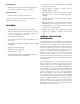
Solid Materials • Output circuits can be made latching or non-latching through field adjustment. — Munitions production such as illuminating flare material, TNT, black powder and other propellants • Keylock switch for setting the controller mode to NORMAL, RESET or TEST. Other Processes • Power supply will accommodate high direct current transients such as those associated with battery charging. • TEST/ACCEPT button for silencing external audible signaling devices.
Nuclear radiation is also a potential cause of false actuation of the detection system. X-rays and gamma radiation easily penetrate the metal housing of the detectors, causing the UV sensor tubes to react in the same way as they would to UV radiation.
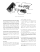
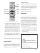
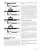
UV DETECTOR TUBE TERMINAL BLOCK QUARTZ WINDOW AND HOUSING Oi REFLECTIVE RING INDEX PIN TERMINAL BLOCK BLINDED WINDOW RADIATION DETECTOR TUBE Figure 2—C7051 Detector Assembly 1. The green POWER LED is illuminated whenever power is applied to the controller. R7404 CONTROLLER Microprocessor technology has made possible a degree of programming flexibility that could not be achieved in previous generations of Det-Tronics systems.
Programming Switches The R7404 is furnished with four rocker switch assemblies that are used to select options such as detectors connected, time delay, fire logic, controller sensitivity, master/slave position and latching/non-latching. Refer to the “Theory of Operation” and “Installation” sections for a detailed explanation of the programming options. It is essential that the controller be properly programmed before applying power to the system.
detects a fire, the zone one output will be activated provided UV radiation is continuously detected for the preselected time delay. If zone three detects a fire at a later time, the microprocessor will again require that UV is detected continuously for the time delay period before activating the zone three output. 2. The alarm output is energized (solid state - open collector). The alarm is activated when any zone detects a fire. 3. The ZONE display shows the number of the first responding zone.
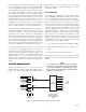
ANY ONE OR MORE ZONES SEE FIRE absorbs as much or more nuclear radiation as the fire detector. Up to four C7051 assemblies can be used with one R7404. ZONE OUTPUT(S) FIRE LOGIC SELECTED ONE ZONE SELECTED? YES The count rate of the blinded detector module corresponds to the intensity of nuclear radiation in the area to be protected. The count rate of the fire detector module corresponds to the intensity of the nuclear radiation plus the UV radiation present in the protected area.
If the STATUS display shows “3” and the ZONE display indicates zones 5 to 8, the blinded surveillance detector indicated may be in a “runaway” state, uncontrollably generating counts. This can be checked by using the count mode test of the controller as described in the “Checkout” section. If the sensor tube in the blinded detector module is in a “runaway” state, it and its counterpart in the fire detector module must be replaced.
VISIBLE ULTRAVIOLET INFRARED 100 75 ATMOSPHERIC TRANSMISSION SOLAR RADIATION REACHING THE EARTH 50 25 B1015 0 0.1 0.2 0.3 0.4 0.5 0.6 0.7 0.8 0.9 1.0 1.5 2.0 3.0 4.0 5.0 WAVELENGTH (MICRONS) Figure 6—UV Detector’s Range of Sensitivity 2. Depress the TEST and SELECT buttons simultaneously and then release. be mounted as close as practical to the probable hazard. Under certain controlled conditions, detectors may be used at greater distances. 3.
An 18 gauge wire from each detector housing to earth ground is required for prevention of false detector actuation due to high electrostatic charges. INPUT VOLTAGE— The R7404 is designed to operate from any voltage in the range of 10 to 38 volts dc. For ac line (mains) voltage operation, an optional voltage converter (model W4220) is available from Det-Tronics. Characteristics of 22 Gauge Copper Wire Metric U.S. Customary Diameter 0.6439 mm 0.02535 Cross Section 0.3255 mm2 0.0005 in2 Resistance 33.
RACK TYPE PART NUMBER 005269-XXX CONTROLLER POSITIONS FOR: FIRE GAS 4U 4U 4U –001 –002 –003 8 6 4 4U 4U 4U –004 –005 –006 3 2 1 HT: DIM. (A) INCH MM DIM. (B) INCH MM DIM. (C) INCH MM DIM. (D) INCH MM DIM. (E) INCH MM WEIGHT LB KG 16 12 8 4U 4U 4U 19.00 15.06 11.13 482.6 382.6 282.6 18.30 14.36 10.43 464.8 364.7 264.9 17.36 440.9 13.42 340.9 9.49 241.1 4.00 6.97 9.3 7.6 5.9 4.2 3.5 2.7 6 4 2 4U 4U 4U 9.16 7.19 5.22 232.7 182.7 132.6 8.46 6.49 4.52 214.9 164.9 114.8 7.52 191.
The UV sensor responds to any radiation which can penetrate its glass envelope and create ion pairs. The glass envelope absorbs most alpha or beta particles, but it permits both gamma and x-rays to pass through. If these rays create ion pairs between the electrodes near the cathode, the normal discharge process will occur and the detector will produce a count.
In general, fire detectors should be placed as close as practical to the probable hazard. The (blinded) nuclear surveillance module of the C7051 Detector must be positioned at least as close, if not closer, to the source of radioactive interference as the fire detector module. See Figure 1. A grounding screw is provided inside the housing for connecting the C7051 to earth ground. It is recommended that a conduit seal, drains and breathers be used.
7. On blinded detector module, slide oi reflector cap over barrel of sensor tube module until firmly seated. Make certain semicircular opening is centered exactly over source tube on sensor tube module. Connect the B-lead shields to connector C in the terminal block. All A-leads go to the A-lead connection in the terminal block. If one C7051 is used, its fire detector module is connected to zone 1 B-lead and D-lead inputs, and its blinded detector module is connected to zone 5 B-lead and D-lead inputs.
SWITCH ASSEMBLY 3 SWITCH ASSEMBLY 1 MASTER/SLAVE SELECTION DETECTOR PAIR SELECTION ROCKER SWITCH 3-8 OPEN: SLAVE – ALL SURVEILLANCE CONTROLLERS EXCEPT FIRST IN SERIES ROCKER 1-4 OPEN: ZONES 4 AND 8 SELECTED ROCKER 1-3 OPEN: ZONES 3 AND 7 SELECTED ROCKER SWITCH 3-8 CLOSED: MASTER – FIRST SURVEILLANCE CONTROLLER IN SERIES ROCKER 1-2 OPEN: ZONES 2 AND 6 SELECTED ROCKER 1-1 OPEN: ZONES 1 AND 5 SELECTED FIRE LOGIC SETTING ROCKER POSITION FIRE LOGIC OUTPUTS 3-6 3-5 3-7 ALL OPEN 1 CLOSED 2 CLOSED 3 CLOSED
Switch 3-8 selects master or slave operation for the controller. NOTE If no rockers are closed, or if only rocker 3-1 is closed, the controller responds to an 8 cps signal from the detector. Closed = master, Open = slave. 5. Outputs Latching/Non-Latching - Switch Assembly Rocker 4-1. Figure 14 is an example of a 24 cps setting.
Table 2—Nuclear Surveillance Controller Terminal Connections It is inadvisable to use the minimum time delay (0.5 second) with the maximum detector sensitivity (8 cps), as this setting increases the possibility of false system actuation. Electrical Terminals CONTROLLER ELECTRICAL CONNECTIONS All electrical connections are made to the plug-in field wiring connector that is furnished with the controller. Figure 18 shows its terminal configuration.
Table 3—Relationship of ZONE Display to the Status Outputs Status Outputs Zone 1 2 3 4 5 6 7 8 Table 4—Relationship of SYSTEM STATUS Display to Status Outputs Front Panel Display S1 S2 S3 S4 1 0 1 0 1 0 1 0 0 1 1 0 0 1 1 0 0 0 0 1 1 1 1 0 0 0 0 0 0 0 0 1 TYPICAL SYSTEM APPLICATION System Status S5 S6 S7 S8 Fault Outputs Inhibited 0 0 0 0 0 0 1 1 0 1 0 0 0 1 2 0 0 1 0 0 0 3 0 1 1 0 x*** 0 4 0 0 0 1 0 0 5 0 1 0 1 0 0 6* 0 0 1 1 1 0 7** 0
19 95-8256 B3 B4 * 16 3 5 * 13 C D5 A B2 C D2 B7 9 * 17 3 B6 C D6 A DATA STROBE DMA IN AVAILABLE 31 32 19 D8 DMA OUT 29 * DMA OUT AVAILABLE 28 C DATA OUTPUT 7 27 63 15 D4 DMA IN DATA OUTPUT 6 26 62 * C 30 DATA OUTPUT 5 25 61 7 B4 11 DATA OUTPUT 4 24 60 3 A B8 DATA OUTPUT 3 23 59 3 DATA OUTPUT 2 22 58 18 D7 A DATA OUTPUT 1 21 57 * DATA OUTPUT 0 20 56 C D1-8 oi DRIVER 19 D8 10 D1-7 oi DRIVER 18 D7 B7 D1-6 oi DRIVER 17 D6 14
14. Controller cycles to next lower zone pair (controller cycles through the detectors selected on rocker switches 1-1 to 1-4). (See “Theory of Operation.”) TESTING OF DETECTOR MODULE RESPONSE TO UV RADIATION (COUNT MODE TEST) 1. Place keylock switch in TEST position. 15. Repeat steps 6 through 14 until all detectors have been checked. At the completion of the sequence, each detector will have been tested for the following conditions: 2. SYSTEM STATUS displays the number “1”. 3.
1. Place the keylock switch in the NORMAL position. VOLTAGES AND WAVEFORMS TO AID IN TROUBLESHOOTING 2. Turn on W8066 UV Test Lamp or an equivalent UV source and shine into any fire detector. A-lead (terminal 3) to circuit ground: +290 vdc. D-lead (terminals 12 through 19) to A-lead: less than 1 volt. 3. If system works correctly, the appropriate ZONE OUTPUT LED turns on and flashes, indicating the zone in which the detector is located. ZONE display shows first zone activated.
DEVICE REPAIR For devices or components in need of repair, contact your local source or return the equipment transportation prepaid to: Detector Electronics Corporation Returned Goods Department 6901 West 110th Street Minneapolis, Minnesota 55438 U.S.A. Table 5—Status Codes - Nuclear Surveillance Controller Upper Displays Lower Display Description Detector Zone Status 0 0 0 Keylock switch is in RESET position, or the external inhibit is activated. (Outputs inhibited, except Status outputs.
+260 VDC 5 to 10 mS + 40 V 0V 5 uS –0 V TEST BUTTON PRESSED TEST BUTTON RELEASED Figure 21—Detector B-lead Waveform Figure 20—Detector D-lead Voltage - Manual Test +VDC 60 VOLT MAXIMUM (MUST BE EXTERNALLY PROVIDED) +VDC LOAD LOAD D G S 100 K Ω SWITCH OUTPUT CIRCUIT 100 K Ω EQUIVALENT CIRCUIT Figure 22—R7404 Solid State Output Circuit +VDC 10K Figure 23—Solid State Input Detector Electronics Corporation 6901 West 110th Street • Minneapolis, Minnesota 55438 • Fax (612) 829-8750 Telephone
Fault Record Sheet Upper Display Date Time Detector Zone Lower Display System Status 24 Operator Comments
Recommended Test Form Date Installed Date Checked Date Lens Cleaned Sensitivity Readings Count Test Mode 25 Remarks 95-8256