
User Manual


2.5 95-86574
ATX10
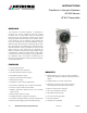
The main function of the ATX10 Transmitter is to evaluate
the incoming acoustic power spectrum data from the
AC100 Acoustic Sensor and make a determination of
alarm condition. The transmitter communicates with the
sensor via proprietary serial connection.
Operating Power
The acoustic detector operates on 24 Vdc nominal (9 to
30 Vdc total range) system power via wired connection
to terminal blocks in the transmitter junction box. The
24 Vdc is also passed through to the sensor unit for
power.
LEDs
The ATX10 includes three local LEDs on the faceplate
to indicate Power (green), Fault (yellow), and Alarm
(red) status.
LED Indication Status
Steady Green Power On
Slowly Flashing Green
(<Once per Second)
Learn Function Active
Rapidly Flashing Green
(Twice per Second)
Manual AIC in Progress
Steady Yellow Critical Fault
Slowly Flashing Yellow
(<Once per Second)
Advisory Fault
Steady Red Alarm
Rapidly Flashing Red
(Twice per Second)
Pre-alarm
See Figure 2 for LED locations.
Magnetic Switches
The ATX10 includes two magnetic switches that
support local initiation of an acoustic test, and clearing
of latched alarms. See Figure 2 for magnetic switch
locations.
4-20 mA Output
The safety function of the detector is communicated via
the 4-20 mA HART output. Valid 4-20 mA outputs and
their meanings are summarized below:
Output Status
1 mA Critcal Fault
2 mA Advisory Fault
4 mA Normal
16 mA Pre-Alarm
20 mA Alarm
Figure 2—Magnetic Switches and LEDs on ATX10 Faceplate
TEST
RESET
ALARM
FAU LT
POWER
TEST SWITCH
FAULT LED
ALARM LED
POWER LED
RESET SWITCH
A2587