RBC1RBC1-50 INSTRUCTION MANUAL C-200 PN 163189 REVISION B 1/2003
Notice Users of this equipment must comply with operating procedures and training of operation personnel as required by the Occupational Safety and Health Act (OSHA) of 1970, Section 6 and relevant safety standards, as well as other safety rules and regulations of state and local governments. Refer to the relevant safety standards in OSHA and National Fire Protection Association (NFPA), section 86 of 1990.
PREFACE This manual is your guide to the Despatch oven. It is organized to give you the information you need quickly and easily. The INTRODUCTION section provides an overview of NOTE: the Despatch oven. Read the entire INTRODUCTION and THEORY The THEORY OF OPERATION section details the OF OPERATION before function and operation of assemblies and installing the oven. subassemblies on the Despatch oven.
TABLE OF CONTENTS PREFACE ....................................................................................................................... 1 INTRODUCTION............................................................................................................. 4 Special Features.......................................................................................................... 4 Specifications ....................................................................................................
Automatic Damper.............................................................................................. 24 Controls and Indicators....................................................................................... 24 Loose Screws, Bolts and Fasteners ................................................................... 24 Lubrication .......................................................................................................... 24 Tests ...................................................
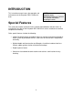
INTRODUCTION This instruction manual covers the operation and maintenance of the Despatch RBC1-50 Burn-In oven. NOTE: Read the entire INTRODUCTION and THEORY OF OPERATION before installing the oven. Special Features The sturdy construction and three-inch insulation top and bottom and four-inches of insulation on the sides of the Despatch RBC1-50 Burn-In ovens contribute to excellent temperature uniformity.
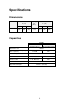
Specifications Dimensions Model RBC1-50 Chamber Size in (cm) W 18 (46) D 25 (64) H 18 (46) Capacity 3 feet (liters) Overall Size in (cm) W 46 (117) 4.7 (133) D 36 (91) H 31.50 (80) Capacities MODEL RBC1-50 Air Atmosphere Maximum Load Fresh Air/ Exhaust Capacity at 125 °C (255 °F) Recirculating Fan RBC1-50 Nitrogen Atmosphere 150 Lbs 51 CFM N/A 600 CFM 1 HP Fresh Air Inlet 2.5” Diameter N/A Exhaust outlet 2.18” Diameter N/A # of Doors Approximate Weight 1 470 Lbs.
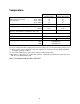
Temperature Time to Temperature (approximate minutes with no live load) (1) 25°C - 80°C 25°C - 125°C 25°C - 150°C 25°C - 260°C Recovery Time to 125°C with door open 1 Min. Temperature Uniformity at (2) 125°C* 260°C* Operating Temperature Range (Based on 25°C ambient, and dampers fully open) RBC1-50 Air Atmosphere 4 10 14 34 RBC1-50 Nitrogen Atmosphere 4 10 14 30 >1 Min. <±1°C ±1°C >1 Min. <±1°C ±1°C 50° - 260°C 15° - 260°C ±0.
Power Line voltages may vary in some geographical locations. If your line voltage is much lower than the oven voltage rating, warm up time will be longer and motors may overload or run hot. If your line voltage is higher than nameplate rating, the motor may run hot and draw excessive amps. If the line voltage varies more than 10% from the oven voltage rating, some electrical components such as relays, temperature controls, etc. may operate erratically.
THEORY OF OPERATION Despatch RBC1-50 Burn-In ovens are made for the accelerated life testing of microcircuit electronic devices to identify early mortality. The Despatch RBC1-50 ovens are ideally suited for: • high-dissipation forward-bias burn-in, • high temperature reverse-bias burn-in, • stabilization baking of integrated circuits and other semiconductor devices. Air atmosphere ovens recirculate air through the chamber. They can add heat and remove dissipated heat.
Power Switch The POWER switch controls power to the control circuit, chamber recirculating fan motor relay, control cabinet fan, and any options that were included at the time of purchase. Air Circulation A Despatch centrifugal fan draws air through the heater section, moves it evenly across the chamber, past the temperature sensors and back to the heater. The fresh air is controlled manually and a modulating damper controls the exhaust.
Chamber Door Handle The door handle positively engages a cam with a catch in one-quarter turn. The silicone rubber gasket provides a seal around the door as the handle is moved to the latched position. Damper Control The oven is equipped with a manually adjustable fresh air damper. The damper blade located on the rear of the oven. The damper adjustment controls the flow of fresh air into the chamber.
Full Open Position When the fresh air damper is in the full open position, the chamber will operate at its minimum operating temperature. Friction heat from the air recirculation system builds up in the chamber. This causes chamber temperature to rise slightly even though the heating system is not turned on. After the recirculation motor has been on for an extended period of time, the chamber will reach a thermal equilibrium temperature.
NOTE: Overpressurizing the chamber can cause hot air to blow out around the door seal and cause the area around the door to be hot to the touch. To stop this hot air from entering the room, close the damper slightly until the air stops blowing.
OVEN INSTRUCTIONS Failure to heed warnings in this instruction manual and on the oven could result in death, personal injury or property damage. WARNING: Do not use oven in wet, corrosive or explosive atmospheres. Unpacking and Inspection Remove all packing materials and thoroughly inspect the oven for damage of any kind that could have occurred during shipment. • See whether the carton and plastic cover sheet inside carton are still in good condition.
Warning Signs Missing If it appears that any warning, danger, caution or information label or sign has been damaged or lost, contact Despatch Industries for replacements. Call or write: Service Products Division Despatch Industries P.O.
Set-up 1. Select the location for installing your oven. 2. Install an exhaust stack from the exhaust discharge stack to the outside of the building, if required. WARNING: Do not use the oven in wet, corrosive or explosive atmospheres. • If a round exhaust stack is used, a minimum area greater than the area of the exhaust stack is required. • The flashing through the roof or wall must be capable of handling an exhaust stack temperature up to 260°C (500°F).
Power Connection Be sure the oven is connected to the power source shown on the nameplate. Connect the oven directly to your electric supply, with all grounding and safety equipment, according to applicable codes, ordinances and accepted safe practices. Line voltages may vary in some geographical locations. If your line voltage is much lower than the oven voltage rating, the warm up time will be longer and the motors may overload or run hot.
Operating Users and operators of this oven must comply WARNING: with operating procedures and training of Do not use oven in wet, corrosive or operating personnel as required by the explosive atmospheres. Occupational Safety and Health Act (OSHA) of 1970, Section 5 and relevant safety standards, and other safety rules and regulations of state and local governments. Refer to the relevant safety standards in OSHA and National Fire Protection Association (NFPA), Section 86 of 1990.
Oven Temperature Limit Do not attempt to exceed the maximum or minimum operating temperature of this oven. Product Temperature Limit If the product has a critical high temperature limit, the HIGH-LIMIT control should be used as a process HIGH-LIMIT. When used as a process HIGH-LIMIT, the control should be set to a temperature somewhat below the temperature at which the product would be damaged. A pyrometer could be used to determine the process HIGH-LIMIT setting.
Pre-Startup Checklist • Know the system. Read this manual carefully. Make use of its instructions and explanations. Safe, continuous, satisfactory, trouble-free operation depends primarily on the degree of your understanding of the system and your willingness to keep all parts in proper operating condition. • Check line voltage. Voltage must correspond to nameplate requirements of motors and controls. Refer to the section on power connections in the INTRODUCTION of this manual. • Fresh air and exhaust.
5. 6. If temperature of the chamber exceeds the high-limit setting on the control, the heater will shut down and the Alarm Horn and red pilot light will energize. The heater will shut off. To silence the alarm: • Depress the Alarm Silence switch, this is a momentary switch, it will return to its normal position when released. • The alarm horn will be silenced, but the red alarm pilot light will remain lit. • When the overtemperature condition clears, press RESET on the control.
Maintenance Do not attempt any service on this oven before opening the main power disconnect switch. WARNING: Disconnect the main power switch or power cord before attempting any repair or adjustment. Checklist • Keep equipment clean. Gradual dirt accumulation retards airflow. A dirty oven can result in unsatisfactory operation such as unbalanced temperature in the work chamber, reduced heating capacity, reduced production, overheated components, etc.
Inspection and Cleaning The purpose of inspection is to determine cleanliness, proper operation and condition of the oven, including its controls indicators and moving parts. Vents Make sure intake and exhaust openings are clean and free of blockages. Any dirt accumulation in the air circuit can unbalance temperatures and airflow patterns. Chamber Keep perforated panels and other surfaces of the chamber clean. Use a vacuum cleaner to clean perforated panels.
Chamber Door Gasket Check the gasket on the chamber door as follows. 1. Open the door. 2. Visually inspect the gasket-sealing surface. 3. Squeeze the gasket between your fingers to check for damage and tears. 4. Close the door on a piece of paper at many points around the gasket. The gasket should seal tight enough to require a slight pull to remove the paper. Recirculation Motor Fans, motors and shaft should be clean and free of dust and oil or grease.
Automatic Damper 1. Put the oven in operation (without a load in the chamber) and wait until the temperature is stabilized. 2. Set the controller to about 10°C lower. 3. While looking at the damper control motor and linkage, when the setpoint is first turned down, the dampers should move to the wide-open position. 4. Then, as the chamber temperature drops, the dampers should start to close when the difference between the chamber temperature and the setpoint is less than 4°C. 5.
Tests Tests should be performed carefully and regularly. The safety of personnel as well as the condition of equipment may depend upon the proper operation of any one of the functions of the temperature control. Test the control every 40 hours. Check that the heater LED is cycling on and off, indicating that the heater is working. Also at this time, check the high limit function to make sure it is working properly. Refer to manufacturer’s instruction manual on the controls, if necessary.
OPTIONAL ACCESSORIES This section provides operating instructions on the standard options for the RBC1-50 Burn-In oven. Door Switch WARNING: Disconnect the main power switch or power cord before attempting any repair or adjustment. The door switch is wired to shut off the fan and heater. In addition, when the N2 and LN2 options are installed the door switch will shut these down. The door switch may be defeated manually by pulling out the actuator.
• The heater should be back on and the chamber should be functioning correctly. If the high-limit trips repeatedly, verify the cause of overtemperature and correct problem. See the manufactures manual on the redundant high-limit instrument attached to this manual. Disconnect Switch The disconnect switch is located on the upper front of the control panel, above the controller. The OFF position is when the handle turned to the left, and ON is when it turned to the right.
Replacement WARNING: Disconnect the main power switch or power cord before attempting any repair or adjustment. Parts To order or return parts, contact the Service Products Division at Despatch. The Service Products Division features our Response Center for customer service. When returning parts, a Despatch representative will provide you with an MRA (Material Return Authorization) number. The MRA number must be attached to the returned part for identification.
Operator Training Requirements Users and operators of this oven must comply with operating procedures and training of operating personnel as required by the Occupational Safety and Health Act (OSHA) of 1970, Section 5 and relevant safety standards, and other safety rules and regulations of state and local governments. Refer to the relevant safety standards in OSHA and National Fire Protection Association (NFPA), Section 86 of 1990.
11. When the chamber temperature is above setpoint on control, the cooling output of the control will start cycling the liquid nitrogen (LN2) solenoid valve, which will cool the chamber. 30 WARNING: Failure to heed this warning can result in severe frostbite to eyes or skin. Do not touch frosted pipes or valves.
Nitrogen Atmosphere Purge Rate The chart below shows the time required to reduce the oxygen content to different percentages of concentration. At a flow rate of 100 SCFH in the RBC1-50 Burn-In oven, oxygen concentration from 21% in room air down to 6% in the closed oven takes approximately 11 minutes.
Maintain Rate The chart below shows typical flow rate required to maintain the oxygen content at different percentages of concentration in the RBC1-50 Burn-In oven with nitrogen atmosphere option installed. For example, it requires 36SCFH to keep the oxygen concentration down to 6½ percent in the closed oven chamber. The preliminary settings can be determined from this graph. If the oxygen concentration must be determined more accurately, use an oxygen monitor. Oxygen Stabilization vs.
Troubleshooting Equipment, which operates for extended lengths WARNING: Disconnect the main power switch of time, may develop problems. Below are or power cord before attempting any possible problems and suggested solutions. If repair or adjustment. you have a problem not listed and do not know what to do, contact Despatch Industries at our toll free Help Line 800-473-7373. Difficulty Failure to heat Slow heat up Frequent heater element burnout Erratic temp. or inaccurate temp.
Difficulty Improper airflow Excessive vibration Oven will not control at setpoint Damper motor (exhaust) not responding Liquid nitrogen (LN2) not cooling Heater does not shut down until temp. reaches the High limit setting Nitrogen (N2) not flowing correctly Probable Cause Fan motor failure Suggested Remedy Replace fan motor. Fan wheel seated too low on fan shaft Adjust fan wheel for 3/16" clearance between wheel and inlet ring. Unbalanced fan wheel Dirty fan wheel Replace fan wheel. Clean fan.
Circuit Board Check The circuit board mounted on the control panel has three status LED indicators to help troubleshoot if the oven is not heating. • If LED 1 is not lit, check 2F and 3F (control fuses), or power switch. • If LED 1 and LED 3 are lit but not LED 2, check high limit (and optional door switch, if installed). If all three LEDs are lit, check 1F and 4F (heater relay fuses), SSR, heater, heater fuses, and heater relay.