PROTOCOL PLUS ™ CONTROL HEAT/COOL VERSION INSTRUCTION MANUAL SOFTWARE VERSION 3.
NOTICE Users of this equipment must comply with operating procedures and training of operation personnel as required by the Occupational Safety and Health Act (OSHA) of 1970, Section 6 and relevant safety standards, as well as other safety rules and regulations of state and local governments. Refer to the relevant safety standards in OSHA and National Fire Protection Association (NFPA), section 86 of 1990.
Despatch Industries Product Warranty See separate warranty for Benchtop and Laboratory Ovens (Form BB7) Parts, Materials and Labor Seller warrants the equipment manufactured by Seller and not by others, to be free from defects in workmanship and material under normal use and service for a period of (1) year from the date of delivery or the period of two thousand (2,000) accumulated hours of use, whichever period is shorter.
Despatch Industries Advantage Service Assurance Program (ASAP) CONTACT: DESPATCH SERVICE AGREEMENTS SPECIALIST at 800-473-7373 or 612-781-5356 or e-mail: info@despatch.com Despatch continues to deliver exceptional products backed by a strong sense of responsibility and drive for long term customer satisfaction. Your partnership with Despatch can offer even higher value through your subscription to one of Despatch's Advantage Service Assurance Program (ASAP).
TABLE OF CONTENTS TABLE OF CONTENTS ................................................................................................... i INTRODUCTION............................................................................................................. 1 Theory of Control Operation ........................................................................................ 1 Operating Modes...................................................................................................... 3 Setup Mode.
ii
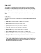
INTRODUCTION The special features of the Protocol PlusTM control include: • • • • • • • • • • • • • PID tuning Ramp/Soak programming of up to 64 segments Segment looping and profile linking Built-in manual reset high limit control Built-in process timer Dedicated LED display for process temperature Multi-purpose two-line LCD display with backlight Auto-tuning Security access Digital inputs for remote profile control Optional relay outputs for events, alarms, or end-of-cycle signal Optional real-time-clock
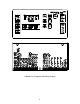
Protocol Plus Faceplate and Wiring Diagram 2
Operating Modes The Protocol Plus control has five modes of operation available: Stopped Mode: All control and relay outputs are off. Stopped Mode is integrated into each of the following four modes of operation. Manual Mode: Control operates as a single setpoint control until Stopped mode is accessed Timer Mode: Control operates as a single setpoint control until preset time period has expired. Profile Mode: Control operates as a ramp/soak profiling control until the end of the profile.
High Limit The control has an integrated high limit function which will disable the heater output when tripped. If the high limit does trip, the relay will need to be manually reset. When the high limit relay is tripped, the Hi-Limit indicator will be lit. Allow the oven to cool several degrees (or increase the high limit setpoint) and then press the Reset key. The indicator will turn off. The control will not allow the high limit setpoint to be set below the current setpoint value.
Displays The Protocol Plus control has two displays. A dedicated LED upper display shows the oven temperature. A two-line LCD lower display provides information on control status and allows changes to be made to the control settings. Key Functions The Protocol Plus control has seven keys that provide operation. • Select key: Press to select mode of operation. In Setup Mode, to select profile number or relay. In Profile/Run Mode, press simultaneously with the UP key to advance a segment.
Outputs The Protocol Plus control has seven different outputs available. • Heating output: The control output is a DC voltage open-collector output which is time-proportioned and designed to control a heat control device such as a solid state relay. • Cooling output: The cooling output is a 4 to 20 ma DC output which is designed to control a cooling device such as a damper motor. • High limit: The high limit output is a form C relay which is energized under normal operating conditions.
Relay (Continued) Use the Relay Card Optional Ay p/n 144562 to add relays to the standard controller. Each relay card contains two relays (maximum of two cards Ay’s allowed). Communication The Protocol Plus control has optional MODBUS communication available which can communicate via RS232, RS422, or RS485 to a computer. See communications option assembly p/n 161957 for board and cable assembly. Please refer to the MODBUS communications manual which comes with this option.
INSTRUCTIONS Start-Up These instructions are provided as a quick reference for operating the Protocol Plus control. If the Profile Mode is to be used, or the configuration of the control needs to be changed, please refer to the Setup Mode instructions before operating the control. For more detailed operating instructions refer to the Operation instructions for the mode you wish to use. Upon initial power-up the control is in Manual/Stopped Mode (unless the Autostart or Fast Start Modes are active).
Operation Manual Mode Press the Select key until Manual is displayed (note you can press the Run key at any time to activate Manual Mode). 1. Press the Menu key to display the Process Temperature Setpoint (setpt). You can change the Setpoint with the keys. Note: If the SPChange parameter on the Enable page in Setup Mode has been set to DISABLED, it must be changed to ENABLED before any changes to the process temperature and high limit setpoints can be made. 2.
Timer Mode 1. Press the Select key until Timer is displayed (note you can press the Run key at any time to activate Timer Mode). 2. Press the Menu key to display the Process Temperature Setpoint (Setpt). You can change the Setpoint with the keys. Note that if the SPChange parameter on the Enable page in Setup Mode has been set to DISABLED, it must be changed to ENABLED before any changes to the process temperature and high limit setpoints can be made. 3.
Profile Mode 1. Press the Select key until Profile is displayed. “None” may be displayed if a profile has not been selected or no profiles entered. 2. Press the key to display the desired profile to run. 3. To start Profile Mode, press the Run key. The display will change from Stop to Run and the segment time remaining, Temperature Setpoint, Profile #, along with the current segment number, will be displayed. To return to Stopped Mode, press the Stop key.
Setup Mode Configuration of the control and programming of the ramp/soak profiles must be done in the Setup Mode. To access Setup Mode, the control must first be in Stopped Mode. 1. Press the Select key until Setup is displayed. 2. Press the Page key and Security will be displayed. 3. Press the Menu key and Password will also be displayed. Use the enter the proper password. keys to 4. Once the proper password is displayed, press the Page key twice to enter the Setup Mode.
Instructions for Setup Mode Pages Program Page Programming of the profiles is provided on the Program Page. Eight profiles are available with up to eight ramp and soak segments per profile. If the optional relay outputs are installed, they must be configured as alarms or events on the Relay Outputs Page before they can be utilized. If configured as event outputs, these relays can be used as time or temperature events.
Menu Item Display Description Ramp Time Seg 1 Pro-1 Seg-1 Ramp Time Ramp time for segment 1 of profile Event 1 Set Value* Pro-1 Seg-1 Ramp Event 1 Event 1 setting for segment 1 ramp of profile Event 2 Set Value* Pro-1 Seg-1 Ramp Event 2 Event 2 setting for segment 1 ramp of profile Event 3 Set Value* Pro-1 Seg-1 Ramp Event 3 Event 3 setting for segment 1 ramp of profile Event 4 Set Value* Pro-1 Seg-1 Ramp Event 4 Event 4 setting for segment 1 ramp of profile Soak Temp Seg 1 Pro-1 Seg 1 So
Profile # There are eight profiles available. Segment# Recipe segments 1 through 8 may be programmed, each with its own set of events, ramp and soak times, and soak temperature. Ramp Time The time required to ramp from one setpoint up to another setpoint. Values between 0 and 59:59 are allowable. In the Protocol Plus controller, the profile ramp and soak times are stored without units. Units are set as either hours and minutes (HH:MM) or minutes and seconds (MM:SS).
Sample Profile Programming Table Profile Number____1______ Segment Time 1 Profile Name__________ Ramp Events 2 3 Soak Temperature 4 Time 1 01h00 100 01h00 2 02h00 50 00h01 3 00h00 4 5 6 7 8 High Limit Setpoint 115 Loop From Seq No Loop To Seq No Loop Number 0 Link To Pro No Guar Soak Band 10 16 Events 1 2 3 4
Auto Start Page (optional) If the optional real time clock has been installed, the Auto Start Page can be configured to automatically start Manual, Timer or Profile Mode at a specified time and day. Note that if Auto Start Enable is set to Yes in the Setup Mode, the Auto Start feature is not turned on - it is available to the operator to be activated in Stopped Mode. To configure the Auto Start feature: 1. Access the Setup Mode. 2. Press the Page key until Auto Start is displayed. 3. Press the Menu key.
Menu Item Display Description Range Enable Autostart Sunday mode Sunday time Monday mode Monday time Tuesday mode Tuesday time Wednesday mode Wednesday time Thursday mode Thursday time Friday mode Friday time Auto Start Enable Enable (yes) or disable (no) the Autostart function Set mode on Sunday to activate No, Yes Set time on Sunday for mode to activate Set mode on Monday to activate 00:00 to 23:59 Set time on Monday for mode to activate Set mode on Tuesday to activate 00:00 to 23:59 Set time
PID Page The PID Page contains parameters which control the response to the setpoint and process variable input. To access the PID Page, enter the Setup Mode. Press the Page key until PID is displayed. Press the Menu key. Each parameter can be changed by pressing the Menu key until the desired parameter is displayed, and then pressing the keys to change the value.
Control Page The Control Page contains various parameters which control miscellaneous functions. To access the Control Page, enter the Setup Mode. Press the Page key until Control is displayed. Press the Menu key. Each parameter can be changed by pressing the Menu keys to change key until the desired parameter is displayed, and then pressing the the value.
Communication Page (optional) The Communication Page contains parameters for the communications feature. To access the Communications Page, enter the Setup Mode (see description earlier in this manual). Press the Page key until Communication is displayed. Press the Menu key. Each parameter can be changed by pressing the Menu key until the desired parameter is displayed, and then pressing the keys to change the value.
Relay Outputs Page (optional) The Relay Outputs Page configures the four alarm/event outputs. Each output has a dedicated indicator light and can be configured as a temperature alarm, profile event, or end of cycle output. Temperature alarms can be of type process high, process low, deviation high, deviation low, or deviation band. To access the Relay Page, enter the Setup Mode (see description earlier in this manual). Press the Page key until Relay is displayed.
Test Page The Test Page contains parameters which allow manual control of the heat control and optional relay outputs and should be used only for testing the functionality of the control instrument. Do not operate the oven for processes using the Test Page. To access the Test Page, enter the Setup Mode (see description earlier in this manual). Press the Page key until Test is displayed. Press the Menu key.
Zone Calibration Page The Zone Calibration Page allows adjustment of the displayed temperature versus the actual temperature measured by the control thermocouple. This may be desirable in certain conditions where the center of the oven chamber is not the same temperature as the control thermocouple. This may occur when the oven is not allowed to soak at a constant temperature for long periods of time, or the oven is being used at high temperature.
As an example, the control is displaying 400°F with the setpoint being 400°F, but the center of the oven chamber is actually 395°F. This can occur due to oven wall losses and product loading variations. The operator may change the zone calibration so that the center of the oven is 400°F when the display re ads 400°F. In this case operate the oven in manual mode with a setpoint of 400°F. Recor d the center of the chamber (as measured with an independent sensor).
Sensor Calibration Page The Sensor Calibration Page has parameters which can change the internal calibration of the temperature sensor input signal. There is a low and high calibration point for both the control sensor and the high limit sensor. To calibrate the instrument, allow the control to warm up for at least 30 minutes. To access the Sensor Calibration Page, enter the Setup Mode (see description earlier in this manual). Press the Page key until Control Sensor is displayed. Press the Menu key.
19. Connect a calibration instrument with a type J thermocouple output to the control sensor input. 20. Connect a voltage measurement device to the retransmit output terminals. 21. Set the calibration instrument output to the temperature value of the RetOutLo parameter from the Control Page. 22. Adjust the RetCalLo * value using the keys until the voltage measurement device reads 1VDC. 23. Press the Menu key. 24.
Enable Page The Enable Page controls access to the other Setup Pages. The setpoint minimum and maximum values, and the security passwords are also set on the Enable Page. To access the Enable Page, enter the Setup Mode using a level 2 access code (see description earlier in this manual). Press the Page key until Enable is displayed. Press the Menu key. Each parameter can be changed by pressing the Menu key until the desired parameter is displayed, and then pressing the keys to change the value.
Digital Inputs (optional) The Protocol Plus control can be run by external inputs wired to the control from an external source such as a PLC or control panel switches. The external run operation can Run, Hold or Stop profiles 1 through 7 (profile 8 can not be operated externally). Refer to the table below for the inputs required for the desired operation. NOTE: A profile must be created in the program page before trying to run a profile number.
Error Messages and Alarms The Alarm Status Hi-limit LED is flashing. This indicates a problem with the thermocouple, or the Hi-limit setpoint has been exceeded. Once the problem has corrected, press the Reset pushbutton. The Alarm Status Soak LED is flashing. This indicates that the oven temperature has not entered or dropped out of the soak band and the soak timer has stopped. The top LED Display reads OPEN. This indicates that either the Control or the Hi-limit thermocouple is disconnected or broken.
Quick Reference and Default Values Program Page Menu Item Ramp Time Seg 1 Display Pro-1 Seg-1 Ramp Time Default 00:00 Event 1 Set Value Pro-1 Seg-1 Ramp Event 1 Off Range 00m00s to 99h59s Off, On Event 2 Set Value Pro-1 Seg-1 Ramp Event 2 Off Off, On Event 3 Set Value Pro-1 Seg-1 Ramp Event 3 Off Off, On Event 4 Set Value Pro-1 Seg-1 Ramp Event 4 Off Off, On Soak Temp Seg 1 Pro-1 Seg 1 Soak Temp 68°F Soak Time Seg 1 Pro-1 Seg 1 Soak Time 00:00 Event 1 Set Value Pro-1 Seg-1 Soak Eve
Programming Table Profile Number__________ Profile Name__________ Segment Time 1 Ramp Events 2 3 Soak 4 Temperature 1 2 3 4 5 6 7 8 High Limit Setpoint Loop From Seq Loop To Seq Loop Number Link To Pro Guar Soak Band 32 Time Events 1 2 3 4
Autostart Menu Item Display Default Range Enable Autostart Auto Start Enable No No, Yes Sunday mode Auto Start Sun Mode Off Off, Manual, Timer, Pro-1 to Pro-8 Sunday time Auto Start Sun Time 00:00 00:00 to 23:59 Monday mode Auto Start Mon Mode Off Off, Manual, Timer, Pro-1 to Pro-8 Monday time Auto Start Mon Time 00:00 00:00 to 23:59 Tuesday mode Auto Start Tue Mode Off Off, Manual, Timer, Pro-1 to Pro-8 Tuesday time Auto Start Tue Time 00:00 00:00 to 23:59 Wednesday mode Aut
Control Menu Item Display Default Range Setting Cycle Time Control Cycle Time 1 1 to 60 seconds High limit setpoint Control Hi-Lim SP Max HiLimSP MinHiLimSP - MaxHiLimSP* High limit band Control Hi-Lim Band Off Off, 3°C to 11°C (5°F to 20°F) Power fail recovery Control PwrFRec Stop Stop, Restart, Hold, Resume Recovery time limit Control PwrFTime 00m00s 00m00s to 99m59s Powerup start enable Control EPwrStrt Dis Dis, En Powerup Start Mode Control StrtMode Off Off, Manual, Timer
Real Time Clock Menu Item Display Default Range Setting Day of the week Clock Day Mon Time of day Clock HH:MM 00:00 Sun, Mon, Tue, Wed, Thu, Fri, Sat 00:00 to 23:59 Reset clock Clock UP to Reset CLK* Ready Ready, Done * if the key is not pressed, the clock values will retain their original values, the display will change to Done if the clock is reset Relay Outputs (optional) Push Select key to select relay.
Test Menu Item Display Default Range Heater output Test HeatOut Off On High limit relay Test HiLimOut Off On Relay 1 output Test Rly1 Out Off On Relay 2 output Test Rly2 Out Off On Relay 3 output Test Rly3 Out Off On Relay 4 output Test Rly4 Out Off On High Limit Sensor Test HL Temp (sensor reading) Setting Zone Cal Menu Item Display Default Range Zone 1 actual Zone Cal Zone1Act 38°C Zone1 displayed Zone Cal Zone1Dis 38°C Zone 2 actual Zone Cal Zone2Act 260°C Zon
Enable Page Menu Item Display Default Range Profiles Enable Profile 1-8 Yes Yes or No Autostart Enable Auto Start No Yes or No PID Enable PID Yes Yes or No Control Enable Control No Yes or No Communication Enable Communication No Yes or No Real Time Clock Enable Clock No Yes or No Relay outputs Enable Relay 1-4 No Yes or No Test Enable Test No Yes or No Zone Calibration Enable Zone Cal No Yes or No Sensor Calibration Enable Sensor Cal No Yes or No Setpoint lower l
Technical Specifications UL, cUL listed: UL file E136675 CE compliance to: • EMC Directive 89-366/EEC • European Standard EN55011/1991 • European Standard EN50082-2/1995 Power supply: • 100 to 240 VAC +10% -15%, 50-60Hz, 30VA Maximum • 12 to 24 VAC/VDC +/-10%, DC to 60Hz, 30VA Maximum Temperature: • Storage -20 to 60°C • Operating 0 to 50°C 90% or less, non-condensing Humidity: Sensor inputs: • • • • • • • Temperature display: • 1 degree resolution (C or F) • Accuracy after calibration of +/- 1ΕC
APPENDIX: Temperature Scale Conversion and Optional MRC5000 Setup Temperature Scale Conversion (C/F) The Protocol Plus controller can be operated in either C or F. The default setting for the controller is C. Changing from one to the other is as follows: 1. Go into the Setup Mode on the controller. 2. Press the Select Key until Setup is displayed. 3. Press the Page key and Security will be displayed. 4. Press the Menu Key and Password will be displayed. Use the arrow keys to enter the proper password.