Protocol Manager Software E-100 Protocol Manager Network Utility Software INSTRUCTION MANUAL E-100 PN 208711 REVISION H 8/2011
Protocol Manager Software E-100 Revision History Revision B C D E F G H Date 8/2011 Author K. Meyer Description Various corrections Various corrections Various corrections Various corrections Various corrections Various corrections Updated for Version 6.
Protocol Manager Software E-100 Thank you for choosing Despatch Industries. We appreciate the opportunity to work with you and to meet your heat processing needs. We believe that you have selected the finest equipment available in the heat processing industry. At Despatch, our service does not end after the purchase and delivery of our equipment. For this reason we have created the Service Products Group within Despatch. The Service Products Group features our Response Center for customer service.
Protocol Manager Software E-100 TABLE OF CONTENTS INTRODUCTION ............................................................................................................. 1 INSTALLATION............................................................................................................... 2 Host Computer Requirements .............................................................................. 2 Installing the Software ..............................................................................
Protocol Manager Software E-100 INTRODUCTION The Despatch Protocol Manager network utility software enables the operation of multiple Protocol Plus controllers from a remote PC. As many as 32 Protocol Plus units may be operated.
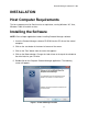
Protocol Manager Software E-100 INSTALLATION Host Computer Requirements The host computer must be Pentium-class or equivalent, running Windows XP, Vista, Windows 7 both 32 and 64 versions. Installing the Software NOTE: Close all open applications before installing Protocol Manager software. 1. Insert the Protocol Manager software CD-ROM into the CD drive of the control computer. 2. Click on the start button in the lower left corner of the screen. 3. Click on the "Run" button from the menu that appears. 4.
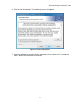
Protocol Manager Software E-100 6. Click on the Next button. The following screen will appear: Figure 2: License Agreement 7. Scroll the window to read the license agreement, then click on the "I accept the terms" button and click Next to continue.
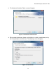
Protocol Manager Software E-100 8. The following Destination Folder screen will appear. Figure 3: Destination Folder Selection 9. Either accept the directory shown and click Next, or select a new directory using the Change button, then click Next. The following screen will appear.
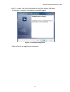
Protocol Manager Software E-100 10. If all is in order, click the Install button to install the software. When the installation is complete, the following screen will appear. Figure 5: Installation Completed 11. Click on Finish to complete the installation.
Protocol Manager Software E-100 Software Setup Configuring the Controllers 1. Use the keys on the faceplate of each Protocol Plus controller to set these parameters. Consult Despatch Manual E98 for information on this process. 2. On each of the controllers, the following parameters must be defined in order for the new control software to communicate with the controllers. Normal conditions use the settings listed in parentheses in the Communication Page in the Setup Mode of the controller.
Protocol Manager Software E-100 Startup and Login 1. Start the application by clicking the Windows taskbar's Start button, then clicking Programs from the menu that appears, then clicking the Protocol Manager option from the list that appears. a. NOTE: The very first time this is done, a prompt may appear that there is no setup information yet, and that the password is despatch. 2.
Protocol Manager Software E-100 Figure 7: User ID after Log in 8
Protocol Manager Software E-100 Setup 1. At this point the system must be set up. Move the cursor to the top of the screen and click on the Window prompt to reach the Setup pulldown. See Figure 8. Figure 8: Setup Pulldown Menu 2. Click on the Setup prompt, and the Software Setup window will pop up. See Figure 9.
Protocol Manager Software E-100 Comm Setup The first tab on the left is the Comm Setup tab. Use the cursor to make selections to allow the computer and Protocol Plus controllers to communicate. Figure 10: Protocol Manager Setup - Comm Setup Tab 1. Port Selection Drop down menu will populate with communication ports. Select the communication port that matches your host computer hardware. 2. Baud Rate 2400 4800 9600 19.2 K 38.
Protocol Manager Software E-100 Select the baud rate that corresponds to the rate programmed into the Protocol Plus controller(s). 19.2 K is the default configuration. 38.4 K provides fastest communication. If the controller(s) will not go on line, try a lower speed. 3. Parity Option None Odd Even Select the parity that corresponds to that which is programmed into the Protocol Plus controller(s). 4. Use Long Timeout Delay checkbox The software uses a timer to check Protocol controller response time.
Protocol Manager Software E-100 Network Setup 1. The second tab from the left on the Software Setup window is the Network tab. Select this tab to add controllers to the system. See Figure 11. Note that if all the buttons are not active, click on the space below the Name to activate the insert button. Figure 11: Protocol Manager Setup - Network Tab 2. Use this screen to add as many controllers as are connected to the host PC.
Protocol Manager Software E-100 Figure 12: Controller Setup Window Name Field: Designate and type in the name of the oven or controller, up to 24 characters long, maximum. Address Field: Type the address or move the slide bar of the Address field to enter the address of the controller. (This field must correspond with the address programmed into the controller on the Communication Page; see Manual E-98 for directions.) Values 1 through 247 are accepted.
Protocol Manager Software E-100 Figure 13: Controller Question Popup 4. Click Yes to add the controller to the network.
Protocol Manager Software E-100 Windows Setup 1. The third tab from the left on the Software Setup window is the Windows tab. This allows the operator to select the parameters that may be viewed from the Network Summary Window and the Controller Run Time window. Press this tab to bring up its screen. See Figure 14.
Protocol Manager Software E-100 2. Click Yes to save settings. Software Setup: Passwords Setup The fourth tab from the left on the Software Setup window is the Passwords tab. Press this tab to bring up its screen. See Figure 15. Three levels of passwords may be set at this screen, which controls the software login level. The highest level, Level 4, enables the user to change communication settings, add/delete controllers from the network, change passwords, and perform all lower-level operations.
Protocol Manager Software E-100 Values from 0 minutes to 60 minutes may be set in the Auto Logoff Time window, which will automatically log the operator off the system after this predetermined period of time. Setting this value to zero disables this feature and the system will not automatically log off. Press the Accept button to save the selected parameters. Press the Restore button to return to the previously saved parameters.
Protocol Manager Software E-100 Network Summary Window Figure 16: Network Summary Window To view the Network Summary Window, click on the Windows prompt to reach Network Summary. Click on the Network Summary prompt, and the Network Summary Window will pop up. See Figure 16. The Network Summary Window simultaneously displays parameters for all the controllers connected in the system.
Protocol Manager Software E-100 Controller Run Time Window Figure 17: Controller Run Time Window The Controller Run Time Window displays current status of an individual controller.
Protocol Manager Software E-100 Network Summary window does not appear in the main menu, click on windows on the task bar and then click on Network Summary on the pull down menu. The Controller Run Time Window initially appears “collapsed” as shown below: Figure 18: Collapsed Controller Run Time Window Double-Clicking the “Cycle COMPLETE” indicator will alternately expand or collapse the Controller Run Time Window.
Protocol Manager Software E-100 Figure 19: Expanded Controller Run Time Window with Datalogs not enabled The expanded window appears as shown in Figure 17 if Lot Datalogs have been enabled (see “Datalog functions”).
Protocol Manager Software E-100 Configuring a Recipe To create a recipe, go to the bar at the top of the screen and pull down to Recipe/ Datalog from the Window designation. The Recipe Editor Window will appear (See Figure 20 and Figure 21).
Protocol Manager Software E-100 Double-click on the fields in the center of the Recipe/Datalog window to bring up a window box to access and change the value shown. Move the slider to change the value quickly. Click on the arrow at either end to change the value by 1. Click in the white space to the left and right of the slider to change the value by 10. Click OK to lock in the change. See Figure 22.
Protocol Manager Software E-100 EV1 through 4 From 1 to 4 events may be programmed into the soak portion of each segment here. These typically involve actuating/disabling relays to close/open valves or perform other relay-controlled functions. NOTE: These will only actuate when the controller has the relay cards installed and programmed for an event. Guaranteed Soak Band If the process temperature deviates from the setpoint by more than this value, the timer is placed in a hold condition.
Protocol Manager Software E-100 Figure 23: MODBUS Comm Error Message Note on Standby Mode In the recipe editor screen, the Link to Profile value “STBY” option (Standby mode) can only be used with Protocol Plus controller version 4 or higher. If a recipe with the Standby mode selected is chosen for download to an earlier version controller, a popup message will be displayed by Protocol Manager, and the downloaded profile will set the Link to Profile value to the “HOLD” option for that controller.
Protocol Manager Software E-100 3. Enter the values desired. 4. Press SAVE to save the recipe. Opening an Existing Recipe 1. Press the OPEN button at the bottom of the Recipe Editor screen. 2. Select the recipe from the popup list.
Protocol Manager Software E-100 Reading/Writing a Recipe to/from a Controller 1. Select the controller from the box at the bottom right corner of the Recipe Editor screen. See Figure 25. Only controllers that are currently enabled and Online will be listed in the box. Figure 25: Read/Write Area, Recipe Editor Screen 2. Select a profile (1 through 8) to be read/written from/to the controller. 3.
Protocol Manager Software E-100 Recipe Selection Setup 1. Go to the second tab from the left at the top of the Recipe Editor screen. 2. Click on this tab and the Recipe Selection screen will pop up. See Figure 26. Figure 26: Recipe Selection Screen The Selectable Recipe Files list indicates which recipes can be selected by name when starting a profile run remotely. Recipes can be added to this list by clicking the "Add" button and selecting a recipe from the list box that pops up.
Protocol Manager Software E-100 the "Selectable Recipe Files" list that will be displayed in the controller start window (see "Starting the Controller").
Protocol Manager Software E-100 Datalog Functions Datalog files are maintained to periodically record controller data to a disk file for future analysis. Protocol Manager can maintain two different types of datalog files from networked controllers. Profile Datalogs – are initiated automatically when a controller is remotely started running, and are closed automatically when the controller stops running. Profile datalogs are useful for jobs that are based on a specific process run.
Protocol Manager Software E-100 The Profile Datalog and Lot Datalog screens are accessed from the tabs at the right side of the initial Recipe Editor screen, off the Recipe/Datalog Window. See Figure 27 and Figure 28. Figure 27: Profile Datalog Window Select the parameters to be written to the datalog by checking the boxes on the Profile Datalog Window screen.
Protocol Manager Software E-100 Log File Record Data Check the following boxes to select the types of data to be written into the log file itself: Elapsed Time Entry Date and Time Temperature Setpoint Temperature Value Alarms and Events Status Recipe Name Log File Folder This field displays the folder used to store datalog files.
Protocol Manager Software E-100 Log File Naming Options Log file names consist of a Controller ID and Time Stamp, created when a data log is started. Controller ID Controller ID identifies the controller by address (three digits with leading zeroes) or name. If name is selected, blank spaces and characters not legal for use in a Windows file name are converted to underscore characters. Time Stamp Select the time format used for the log entries.
Protocol Manager Software E-100 Figure 28: Lot Datalog Window The Lot Datalog screen enables datalog functions to be selected on a per-job basis rather than for all jobs.
Protocol Manager Software E-100 STARTING THE CONTROLLER The controller is started by using the Controller Run Time Window(s) which are accessed from the Window pulldown off the main screen. Start the profile by pressing the RUN/HOLD button at the top right portion of the Controller Run Time window. The Start Running screen will appear. See Figure 29. Figure 29: Controller Run Time Window NOTE that the operator need not be logged in to start or run the controller from the Run Time Window.
Protocol Manager Software E-100 Run Time Window Three different modes of operation are available as tabs from the Start Running screen: Manual mode Timer mode Profile Mode Manual Mode Figure 30 illustrates the Manual operating mode. The process run is held at a single setpoint temperature until the STOP button is pressed at the Controller Run Time Window. Process setpoint, hi-limit setpoint and event status may be entered in the appropriate fields.
Protocol Manager Software E-100 Timer Mode Figure 31 illustrates Timer Mode. This mode allows the operator to start and stop the process for a preset length of time. Figure 31: Start Running Screen - Timer Mode The timer mode is similar to the manual mode except that the time at temperature is added. If the soak band temperature deviates from this setting, the timer is placed in a hold condition.
Protocol Manager Software E-100 Profile Mode Figure 32 illustrates Profile Startup Mode with the "Start Profile by Number" option selected (see "Recipe Selection Setup"). In this mode, one of eight separate profiles (recipes) may be run. Profiles are created or added to the system at the Recipe Editor Screen (Figure 21). NOTE that if a profile number is selected here, but was not created and stored, the profile will not start.
Protocol Manager Software E-100 Figure 33 illustrates Profile Mode startup with the “Start Profile by Recipe Name” option selected (see “Recipe Selection Setup"). Figure 33: Profile Mode Startup with "Start Profile by Recipe Name" NOTE: The list of recipes shown is created from the collection of recipes that have been stored locally. Selecting to start a profile using a recipe from this list will first cause the recipe to be downloaded to the controller as Profile 8, then Profile 8 will be started.
Protocol Manager Software E-100 COMMUNICATION CARD INSTALLATION AND JUMPER SETTINGS Wiring Diagrams Figure 34: RS232 Wiring Figure 35: RS422A Wiring (4 wire) Figure 36: RS485 Wiring (2 wire) 40
Protocol Manager Software E-100 WARNING Electronic components are extremely sensitive to static electricity. Before opening the controller case, read and follow the precautions below to prevent damage from static electricity. 1. Turn off power to the controller. 2. Touch a bare metal surface on the exterior of the controller. 3. Disconnect the power connection from the controller or unplug from the power source.
Protocol Manager Software E-100 Figure 37: Controller rear view with Communications Card (left) 42
Protocol Manager Software E-100 Communication Card Jumper Settings 1. Turn off power to the controller. 2. Remove the back cover of the controller (if it is not already removed) by removing the two screws at the top of the unit. 3. Set the jumpers on the communication card for the desired serial communication interface based on Figure 40, Communication Card Jumper Settings, below. 4. Reinstall the back cover. 5. Reapply power to the controller.
Protocol Manager Software E-100 Connecting Protocol Plus Controller(s) to a Communications Host PC Single Oven If the oven purchased was not supplied with communication option, order Despatch RS232 communication kit P/N 161968. This kit contains all the parts required for one oven to host PC via RS-232 including: Protocol Plus add-on communications board, oven internal cabling, 25 foot null modem cable and Modbus protocol instruction manual.
Protocol Manager Software E-100 network ports; “Communication In” and “Communication Out”. For shorter networking runs, standard serial communication rated cables are available in a variety of lengths. For example; Despatch P/N 161970 is a 25 foot serial cable. DB9 termination plugs are also available from Despatch including P/N 161969; the required termination for a RS422 4-wire network. See remaining information if longer network cable lengths are required.
Protocol Manager Software E-100 Figure 39: Junction Box Wiring 46
Protocol Manager Software E-100 The junction boxes are used to provide a drop from the network cable to each Oven. The cables marked "To Oven Controller" are each terminated with a 9-pin Male subminiature "D" plug, for mating with the Oven Controller's serial data receptacle. Wire the drop cable according to the following table: Oven Signal Junction Box Terminal 9-Pin Plug Pin Number Rcv + 5 2 Rcv - 4 7 Xmit + 1 3 Xmit - 2 4 Gnd 3 5 The daisy-chain and drop cables may use shielded pairs.
Protocol Manager Software E-100 TROUBLESHOOTING THE COMMUNICATIONS OPTION Controller Parameters (see Protocol Plus manual to enter Communications Page) Address (Default = 1) This setting must be different on each control/oven if using RS422/RS485 interface. Mode (Default = OFF) This must be set to Modbus. Baud Rate (Default = 19.2K) If you are having problems going to a lower baud rate may help, but do not change to start with. Parity (Default = None) This should remain the default.
Protocol Manager Software E-100 5. Click on the Network tab and highlight the oven you are trying to setup. Click on the Edit button.
Protocol Manager Software E-100 6. Make sure the address matches and the password is set to the level 2 password of the controller (Default = 2). The enable communications box should be checked. Click on OK when finished. The software should now show a green ON-LINE. If not, check the hardware and cabling.
Protocol Manager Software E-100 Controller Hardware and Cabling Check the communications card The card needs to be installed correctly (jumpers are on the bottom of the card and should be facing the green terminals) The jumpers need to be setup for RS232 or RS422, depending on the interface being used. See Modbus User’s Programming manual (E102) for proper settings. Check cabling between the controller and outside of oven The R+ should be connected to terminal #1 on the back of the controller.
Protocol Manager Software E-100 Despatch kit p/n 161968 includes all parts required to make one oven communicationready. The kit also contains a 25-foot cable (p/n 161971) for PC-to-oven communication. RS422/485 INTERFACE The typical wiring scheme is shown on the next page using wiring kit p/n 161955. Additional ovens (maximum of 32 ovens) can be added using wiring kit p/n 161956.
Protocol Manager Software E-100 53