Protocol Manager Instruction Manual Version 1 PROTOCOL MANAGER NETWORK UTILITY SOFTWARE INSTRUCTION MANUAL PREFACE 1 E-107 PN 324870 REVISION 1 3/2013 Copyright © 2013 by Despatch Industries. All rights reserved.
PREFACE 2 Protocol Manager Instruction Manual Version 1 Revision History Revision B C D E F G H 1 Date 8/2011 3/2013 Author K. Meyer K. Livingston Description Various corrections Various corrections Various corrections Various corrections Various corrections Various corrections Updated for Version 6.0 For use with Protocol Plus and Protocol 3 controllers Copyright © 2013 by Despatch Industries. All rights reserved.
Protocol Manager Instruction Manual Version 1 Table of Contents 1. About This Manual ............................................................................................................. 6 1.1. Important User Information ..................................................................................... 6 1.2. Manufacturer & Service .......................................................................................... 7 1.3. Organization of this Manual ........................................
PREFACE 4 Protocol Manager Instruction Manual Version 1 5. 6. 4.2.1.2. Starting with Timer Mode ............................................................................. 41 4.2.1.3. Starting with Profile Mode ............................................................................ 41 Troubleshooting................................................................................................................ 43 5.1. Controller Firmware Revision ..................................................
Protocol Manager Instruction Manual Version 1 Figure 31. Run in Manual Mode. .................................................................................................. 40 Figure 32. Run in Timer Mode. ..................................................................................................... 41 Figure 33. Run in Profile Mode (typical screens). ........................................................................ 42 Figure 34. Log in at highest security level. ..........................
ABOUT THIS MANUAL 6 1. Protocol Manager Instruction Manual Version 1 About This Manual 1.1. Important User Information Copyright © 2013 by Despatch Industries. All rights reserved.
Protocol Manager Instruction Manual Version 1 ABOUT THIS MANUAL 7 Danger! Only fully-trained and qualified personnel should setup and maintain this equipment. Improper setup and operation of this equipment could cause an explosion that may result in equipment damage, personal injury or possible death. The information in this document is not intended to cover all possible conditions and situations that might occur.
ABOUT THIS MANUAL 8 Protocol Manager Instruction Manual Version 1 Danger! Failure to heed warnings in this instruction manual and on the oven could result in personal injury, property damage or death. 1.4. Conventions This icon signifies information that describes an unsafe condition that may result in death, serious injury, or damage to the equipment.
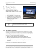
Protocol Manager Instruction Manual Version 1 2. THEORY OF OPERATION 9 Theory of Operation 2.1. Protocol Manager Software The Despatch Protocol Manager network utility software enables the operation of up to 32 Protocol 3 and/orProtocol Plus controllers from a single, remote PC.
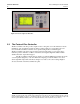
THEORY OF OPERATION 10 Protocol Manager Instruction Manual Version 1 Figure 2. Protocol 3 Operator Interface. 2.3. The Protocol Plus Controller The Protocol Plus controller provides outputs for the cooling fan, door lock switch/door release pushbutton, and optional beacon light. As many as eight profiles for oven heating cycles are stored in the Protocol Plus controller. Access profiles using the Protocol Plus keypad.
Protocol Manager Instruction Manual Version 1 THEORY OF OPERATION 11 Figure 4. Protocol Plus Displays and Control Buttons. Figure 3. Protocol Plus Controller Faceplate. Copyright © 2013 by Despatch Industries. All rights reserved.
INSTALLATION & SETUP 12 3. Protocol Manager Instruction Manual Version 1 Installation & Setup Installation and Setup provides directions for installing and connecting the Protocol Manager software. “Profile” and “Recipe” are used interchangeably throughout the Protocol 3, Protocol Plus, Protocol Manager to indicate those instructions assigned to carry out certain processes. 3.1.
Protocol Manager Instruction Manual Version 1 INSTALLATION & SETUP 13 3.2.2. Configure the Protocol Plus Controller Assign a unique address to each controller and set other communication parameters. Use these typical settings unless setting up a customer application: 1. Enter the Setup mode 2. Press Page until Communication displays 3. Press Menu If the display does not change, the controller does not have the communication board installed. 4.
INSTALLATION & SETUP 14 Protocol Manager Instruction Manual Version 1 b. Locate Despatch Protocol Manager 5. Double-click Despatch Protocol Manager application to show the installer welcome screen (Figure 5) 6. Click Next to display the License Agreement (Figure 6). 7. Scroll down to read the agreement and accept the terms of the license agreement by clicking next to I accept the terms in the license agreement. a. Print a copy for your records. 8. Click Next to continue Figure 6.
Protocol Manager Instruction Manual Version 1 INSTALLATION & SETUP 15 11. If the Install screen is accurate, press Install. a. Otherwise press Back to return to previous screens and correct information. Figure 8. Install Screen. Copyright © 2013 by Despatch Industries. All rights reserved.
INSTALLATION & SETUP 16 Protocol Manager Instruction Manual Version 1 After the installation has completed, click Finish on the InstallShield Wizard Completed screen (Figure 9). Figure 9. Installation Completed Screen. 3.4. Protocol Manager Software Setup After installing the Protocol Manager software and configuring the controllers, setup the network. 3.4.1. Startup and Login This procedure uses the Protocol Manager Software installed on a PC. 1. Start Protocol Manager a. Click Start b.
Protocol Manager Instruction Manual Version 1 INSTALLATION & SETUP 17 Login requires an Operator ID and Password. The Operator ID is case-sensitive and up to 16 characters long. The default password is “despatch” b. Complete the login dialogue box (Figure 10) with appropriate Operator ID and Password. c. After successful login, a User ID box will appear in the screen’s upper left corner (Figure 11).
INSTALLATION & SETUP 18 Protocol Manager Instruction Manual Version 1 Figure 13. Software Setup Window. 2. Click Comm Setup and use the cursor to make the following selections—corresponding to the selections made on each Protocol 3/Protocol Plus controller (Figure 14). a. Select appropriate port from Port Selection drop down menu (Figure 14). Select the communication port that matches your host computer hardware. b. Select Baud Rate.
Protocol Manager Instruction Manual Version 1 INSTALLATION & SETUP 19 controllers. Default Use Long Timeout Delay is checked. e. Press Accept to save the parameters. If the controller will not go online, try a lower Baud Rate. 3.4.3. Network Tab Setup Use the Network tab to prepare the Protocol Manager software to communicate with the network of controllers. 1. Click Window (above the User ID) and then Setup (Figure 12) to display the Protocol Manager Setup Window (Figure 15). 2.
INSTALLATION & SETUP 20 Protocol Manager Instruction Manual Version 1 a. Select the first blank line by clicking on it. b. Press Insert to display the Controller Setup dialogue window (Figure 16). 4. Complete the information in the Controller Setup Dialogue Window using Table 2. Note that the Protocol Plus also requires a password (default value is 2). Click “Yes” for the additional dialogue window. Protocol 3 Controller Setup Protocol Plus Controller Setup Figure 16.
Protocol Manager Instruction Manual Version 1 Set/Cancel INSTALLATION & SETUP 21 Communication), communication between the Protocol Manager and an individual controller will not be attempted. Disabling a controller may be desirable if an oven is shut off or not used for a long period of time. After entering the desired parameters, click Set save the parameters. Click Cancel to delete changes. Click Yes in the dialogue window to add the controller to the network (Figure 16). 3.4.4.
INSTALLATION & SETUP 22 Protocol Manager Instruction Manual Version 1 Figure 17. Windows Tab. Protocol Plus Controller Only: When the controller is running in Timer or Profile mode, click Run/Hold to put the process in Hold. Disable this function so it remains a Run only button by checking the box next to DISABLE Process HOLD Function. 3.4.5. Passwords Tab Setup Use the Passwords tab to select software login levels for the Protocol Manager Software.
Protocol Manager Instruction Manual Version 1 INSTALLATION & SETUP 23 1. Click Window (above the User ID) and then Setup (Figure 12) to display the Software Setup Window. Press Windows to display the Passwords Tab Dialogue Box (Figure 18). Figure 18. Passwords tab dialogue box. 2. Set Auto Logoff Time: time period before the operator is logged off a. Set a value from 0 minutes to 60 minutes by sliding the bar. b.
INSTALLATION & SETUP 24 Protocol Manager Instruction Manual Version 1 3.5. Network Summary Window Click Window and then Network Summary to display the Network Summary Window (Figure 19). Figure 19. Network Summary Screen. Network Summary Window simultaneously displays parameters for all controllers connected in the system.
Protocol Manager Instruction Manual Version 1 INSTALLATION & SETUP 25 Operator ID Lot Information Set the Controller Run Time Window parameters by selecting among the check boxes in the Windows Tab (Section 3.4.4). Note that if the Lot Datalogs box has not been enabled, the Controller Run Time Window as in Section 3.8 Datalog Functions. Figure 20. Controller Run Time Window.
INSTALLATION & SETUP 26 Protocol Manager Instruction Manual Version 1 3.7. Set Up Initial Recipe Recipes establish time and temperature instructions for each controller. Setting up Protocol Manager involves configuring recipes and then selecting the proper recipe for each use. Creating recipes with the Protocol 3 controller follows a different process then creating recipes with the Protocol Plus controller. 3.7.1. Set Up Initial Recipe: Protocol 3 3.7.1.1.
Protocol Manager Instruction Manual Version 1 INSTALLATION & SETUP 27 Table 4. Protocol 3 Controller Recipe Editor Fields and Descriptions. Field Description Parameters Recipe Name of new recipe Defaults to “NEW.” Replace with desired name. Name being created Seg # Shows the number From 1-255 of the profile segment being created Type Set the segment Ramp Time: time to reach target SP type.
INSTALLATION & SETUP 28 SAVE READ WRITE Protocol Manager Instruction Manual Version 1 Saves a recipe to the host PC Reads (uploads) a recipe from the desired controller. Writes (downloads) a recipe to the desired controller 3.7.1.2. Save Initial Recipe: Protocol 3 After keying in the desired recipe using Recipe Editor, press SAVE and identify the desired Recipe Folder (Figure 22). Note that recipes are saved only to the Recipe Folder location, not to the Protocol 3 controller itself. 3.7.1.3.
Protocol Manager Instruction Manual Version 1 3.7.2.1. INSTALLATION & SETUP 29 Configure Initial Recipe (Protocol Plus) Create a recipe by clicking on Window and selecting Recipe/Datalog for Protocol Plus (Figure 21). The Recipe Editor Screen will appear (Figure 24). Double click any field on the Recipe Editor screen to access an editing window. Move the slider or click in the white space or on the arrows to set the appropriate value. Click OK to save the value (Cancel to delete).
INSTALLATION & SETUP 30 Protocol Manager Instruction Manual Version 1 MODBUS Comm Error Message If a recipe Ramp Time, Soak Temp or Hi Limit SP value entered using the Recipe Editor is incompatible with the internally-set range for the target controller, the following error message displays: If the message appears, no changes will be made to the Controller profile. Copyright © 2013 by Despatch Industries. All rights reserved.
Protocol Manager Instruction Manual Version 1 INSTALLATION & SETUP 31 Incompatible Link to Profile Option Message The Link to Profile value STBY (Standby mode) can only be used with Protocol Plus controller version 4 or higher. If a recipe with Standby mode selected is chosen for download to an earlier-version controller, Protocol Manager displays this message: The downloaded profile Link to Profile is set to HOLD for that controller. Table 5.
INSTALLATION & SETUP 32 Protocol Manager Instruction Manual Version 1 Field Description Soak Time Time required to ramp setpoint to temperature Guaranteed Soak Band If the process temperature deviates from the setpoint by more than this value, the timer is placed in a hold condition. The timer continues when the process temperature falls within range. If the temperature exceeds this value, the hi2 limit will alarm and shut off the heater.
Protocol Manager Instruction Manual Version 1 Field Description INSTALLATION & SETUP 33 Parameters selected viewing units. Note that changing the display units converts displayed recipe temperatures accordingly. OPEN SAVE READ Opens a recipe saved to the host PC Saves a recipe to the host PC Reads (uploads) a recipe from the desired controller.
INSTALLATION & SETUP 34 Protocol Manager Instruction Manual Version 1 3.7.2.5. Read a Recipe from the Protocol Plus Controller Protocol Manager can read recipes residing on the Protocol 3 controller. Press READ from the Recipe Editor to load all the existing recipes from the desired Protocol Plus controller (identified in pull down menu, Figure 24). 3.8. Datalog Functions Datalog files periodically record controller data to a disk file for future analysis.
Protocol Manager Instruction Manual Version 1 Table 6. Profile Datalog Tab.
INSTALLATION & SETUP 36 Protocol Manager Instruction Manual Version 1 For a controller named "East Fab #1" with an address of 2, a datalog file name would either begin with "002" (if Address selected) or "East_Fab_#1" (if Name selected). For a run started on February 4th, 2000, at 2:13:45 pm, the Time Stamp would be either "000204" (if YYMMDD selected), "00020414" (if YYMMDDhh selected), "0002041413" (if YYMMDDhhmm selected), or "000204141345" (if YYMMDDhhmmss selected).
Protocol Manager Instruction Manual Version 1 INSTALLATION & SETUP 37 3.8.2. Configure Lot Datalog Check Enable Lot Datalogs to allow datalog functions to be selected on a per-job basis rather than for all jobs (Figure 26). Choose the desired Log Entry Interval value and whether that value is in Seconds or Minutes. Press Accept to save changed values or Restore to return to previously saved values. Figure 26. Lot Datalog Screen. Copyright © 2013 by Despatch Industries. All rights reserved.
Starting the Controller 38 4. Protocol Manager Instruction Manual Version 1 Starting the Controller 4.1. Working with Recipes and Profiles “Profile” and “Recipe” are used interchangeably throughout the Protocol 3, Protocol Plus, Protocol Manager to indicate those instructions assigned to carry out certain processes. 4.1.1. Create a New Profile For help creating recipes consult Section 3.7. 4.1.2. Open an Existing Saved Recipe 1. Press OPEN on the Recipe Editor screen. 2.
Protocol Manager Instruction Manual Version 1 Starting the Controller 39 Figure 28. Network Summary Screen. Double-click on the desired oven to open the Controller Run Time Window (Figure 29). Press RUN to start the manual, timer or profile mode, choose desired dataloging options. Figure 29. Protocol Plus Controller Run Time Window. The user need not log in to start or run the controller from the Run Time Window. However, the Start Running screen requires an login.
Starting the Controller 40 Protocol Manager Instruction Manual Version 1 4.2.1. Start Controller in the Run Time Window The Run Time Window presents three options for starting a profile (Figure 30): Manual Mode Time Mode Profile Mode 4.2.1.1. Starting with Manual Mode Figure 30. Run Time Window showing manual tab. In Manual Mode the process run is held at a single setpoint temperature until the operator presses STOP (Figure 31).
Protocol Manager Instruction Manual Version 1 4.2.1.2. Starting the Controller 41 Starting with Timer Mode Timer mode allows the operator to start and stop the process for a preset length of time (Figure 32). Timer mode is similar to Manual mode except that the time at temperature is added. If the soak band temperature deviates from this setting, the timer is placed in a hold condition. Figure 32. Run in Timer Mode. 4.2.1.3.
Starting the Controller 42 Protocol Manager Instruction Manual Version 1 If a profile number is selected, but that profile has not been created and stored, the profile will not start. Figure 33. Run in Profile Mode (typical screens). The list of recipes shown is created from the collection of recipes stored locally. Selecting to start a profile using a recipe from this list will first cause the recipe to be downloaded to the controller as Profile 8, then Profile 8 will be started.
Protocol Manager Instruction Manual Version 1 5. TROUBLESHOOTING 43 Troubleshooting 5.1. Controller Firmware Revision Refer to the Protocol 3 Controller Owner’s Manual for instructions on how to enter Product Information. Protocol Manager Software requires Version 2.3 or later firmware for the Protocol 3 controller. If the control is version 2.2 or earlier contact Despatch for a replacement. 5.2.
Troubleshooting 44 Protocol Manager Instruction Manual Version 1 2. Click on Window and Setup (Figure 35) to get to Comm Setup (Figure 36). Figure 35. Window Pull Down Menu. Figure 36. Comm Setup Typical Settings. 3. Click on Network and highlight the desired oven. Click Edit. Make sure addresses on the Protocol Manager screens match the addresses on each controller (Figure 37). For Protocol Plus controllers, ensure the password is set to the default (Level 2). Enable Communication should be enabled.
Protocol Manager Instruction Manual Version 1 TROUBLESHOOTING 45 Figure 37. Check network controller parameters. 4. When the Rum Time Window green On-Line light comes on, communication has been successfully established (Figure 38). If Online does not light, check hardware and cabling (Section Error! Reference ource not found.). Figure 38. Run Time Window Online light indicates successful communication with controllers. 5.4. Controller Hardware and Cabling 5.4.1.1.
Troubleshooting 46 Protocol Manager Instruction Manual Version 1 Figure 39. Check Cabling Between Controller and Oven. 5.4.1.2. Check Cabling between Computer and Outside of Oven Typical wiring schemes are shown in Figure 40, Figure 41 and Figure 42 . There may be a combination of protocol plus and protocol 3 controllers. Additional ovens (maximum of 32 ovens) can be added. Contact Despatch Service for more information (see Section 1.2). Copyright © 2013 by Despatch Industries. All rights reserved.
Protocol Manager Instruction Manual Version 1 TROUBLESHOOTING 47 Figure 40. Older model serial converter. Copyright © 2013 by Despatch Industries. All rights reserved. No part of the contents of this manual may be reproduced, copied or transmitted in any form or by any means including graphic, electronic, or mechanical methods or photocopying, recording, or information storage and retrieval systems without the written permission of Despatch Industries, unless for purchaser's personal use.
Troubleshooting 48 Protocol Manager Instruction Manual Version 1 Figure 41. Newer model serial converter. Copyright © 2013 by Despatch Industries. All rights reserved. No part of the contents of this manual may be reproduced, copied or transmitted in any form or by any means including graphic, electronic, or mechanical methods or photocopying, recording, or information storage and retrieval systems without the written permission of Despatch Industries, unless for purchaser's personal use.
Protocol Manager Instruction Manual Version 1 TROUBLESHOOTING 49 Figure 42. USB Converter. Copyright © 2013 by Despatch Industries. All rights reserved. No part of the contents of this manual may be reproduced, copied or transmitted in any form or by any means including graphic, electronic, or mechanical methods or photocopying, recording, or information storage and retrieval systems without the written permission of Despatch Industries, unless for purchaser's personal use.
Troubleshooting 50 Protocol Manager Instruction Manual Version 1 Copyright © 2013 by Despatch Industries. All rights reserved. No part of the contents of this manual may be reproduced, copied or transmitted in any form or by any means including graphic, electronic, or mechanical methods or photocopying, recording, or information storage and retrieval systems without the written permission of Despatch Industries, unless for purchaser's personal use.
Protocol Manager Instruction Manual Version 1 6. APPENDICES 51 Appendices 6.1. Protocol Plus Communication Card Installation And Jumper Settings Electronic components are extremely sensitive to static electricity. Before opening the controller case, read and follow the precautions below to prevent damage from static electricity. Notice 1. Turn off power to the controller. 2. Touch a bare metal surface on the exterior of the controller. 3.
APPENDICES 52 Protocol Manager Instruction Manual Version 1 6.1.1. Communication Card Installation 1. Turn off power to the controller. 2. Remove the back cover of the controller by removing the two screws at the top of the unit. 3. Looking into the back of the controller with the connector terminal strips at the bottom: a. Install the communication card onto the two 5 pin headers on the rear circuit board. b.
Protocol Manager Instruction Manual Version 1 APPENDICES 53 Figure 44. Communication Card Jumper Settings. 6.1.2. Communication Card Jumper settings. 1. Turn power to the controller OFF. 2. Remove the back cover of the controller (if it is not already removed) by removing the two screws at the top of the unit. 3. Set the jumpers on the communication card for the desired serial communication interface based on Figure 44. 4. Reinstall the back cover. 5. Reapply power to the controller. 6.1.3.
APPENDICES 54 Protocol Manager Instruction Manual Version 1 RS422A Wiring Diagram (Figure 46) RS 485 Wiring Diagram (Figure 45) Figure 47. RS232 Wiring. Figure 46. RS422A Wiring (4 wire). Figure 45. RS485 Wiring (2 wire). Copyright © 2013 by Despatch Industries. All rights reserved.
Protocol Manager Instruction Manual Version 1 APPENDICES 55 6.1.4. Connecting Controllers to a Communications Host PC If the ovens purchased were not supplied with communication options, order additional components (add-on Protocol Plus communication board, internal cabling, DB9 external cable connections) to make the ovens communication-ready. Order components required to network two ovens to a host PC. Contact Despatch Service for more information (see Section 1.2). 6.1.4.1.
APPENDICES 56 Protocol Manager Instruction Manual Version 1 simplified network wiring diagram). In this case, "To Host PC" actually indicates a cable connection to the B&B adapter. The "PC Rcv" and "PC Xmit" terminals refer to the B&B adapter's RD and TD terminals respectively. Install the 120 ohm resistor between the RD+ and RD- terminals. Connect the GND wire to the 422/485 GND terminal. The remaining termination resistor is applied at the RD+ and RD- terminals of the “last in line” networked oven.
Protocol Manager Instruction Manual Version 1 APPENDICES 57 The daisy chain drop cables may use shielded pairs. Cable shields should be connected as follows: At each junction box - to the box interior chassis. At each drop cable 9-in plug-to the lug shell if conductive. If a non-conductive shell is used, no connection is required. Copyright © 2013 by Despatch Industries. All rights reserved.
APPENDICES 58 Protocol Manager Instruction Manual Version 1 Copyright © 2013 by Despatch Industries. All rights reserved. No part of the contents of this manual may be reproduced, copied or transmitted in any form or by any means including graphic, electronic, or mechanical methods or photocopying, recording, or information storage and retrieval systems without the written permission of Despatch Industries, unless for purchaser's personal use.