MIC 1462 SETPOINT PROGRAMMER INSTRUCTION MANUAL i E-91 PN 136109 REVISION 10-07
ii
TABLE OF CONTENTS SECTION 1: PRODUCT DESCRIPTION ....................................................................... 1 1.1 General ................................................................................................................. 1 1.2 Displays................................................................................................................. 2 1.3 Control................................................................................................................... 2 1.
SECTION 4: ACCESSING MODES OF THE CONTROLLER ..................................... 37 SECTION 5: USING THE PRETUNE AND AUTOTUNE FEATURES ......................... 39 5.1 Using The Pre-Tune Facility................................................................................ 39 5.2 Using The Auto-Tune Facility .............................................................................. 39 SECTION 6: PROFILE SET MODE ............................................................................. 41 6.
SECTION 1: PRODUCT DESCRIPTION 1.1 General This instrument is a powerful, easy-to-use 1/4 DIN setpoint programmer with full PID control capability (complete with Self-Tune and Pre-Tune facilities). Control functions, alarm settings and other parameters are easily entered through the front keypad. E2 Technology (100 year life) protects against data loss during AC power outages. The input is user configurable to directly connect to either thermocouple, RTD, MVDC, VDC or mADC inputs.
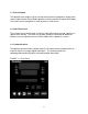
1.2 Displays Each instrument is provided with two main displays, a message display, and status indicators as shown in Figure 1 -1. The upper main display shows the value of the process variable. The lower main display shows the setpoint value. The message display shows parameter tag names and mode list items during various modes of operation. 1.3 Control The instrument can be programmed for on-off, time proportioning, or current proportioning control implementations depending on the model number.
1.7 Event Outputs The optional event outputs may be used to control external components during either single setpoint control (Base Mode) operation or during a profile (Program Run Mode). The events can be configured as timed or process value events. 1.8 Real-Time Clock The instrument may be fitted with a real-time clock which allows starting a profile at a specific time and day.
4
SECTION 2: INSTALLATION & WIRING 2.1 Unpacking Procedure 1. Remove the instrument from its packing. The instrument is supplied with a panel gasket and push-fit strap. Retain the packing for future use, should it be necessary to transport the instrument to a different site or return it to the factory for repair/testing. 2. Examine the delivered items for damage or deficiencies. If any is found, notify the carrier immediately.
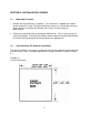
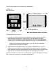
The main dimensions of the instrument are shown below. FIGURE 2-2 Main Dimensions To panel-mount the instrument: 1. Insert the rear of the instrument housing through the cutout (from the front of the mounting panel) and hold the instrument lightly in position against the panel. Ensure that the panel gasket is not distorted and that the instrument is positioned squarely against the mounting panel. Apply pressure to the front panel bezel only.
FIGURE 2-3 Panel-Mounting the Instrument 2.3 Wiring Guidelines Electrical noise is a phenomenon typical of industrial environments. The following are guidelines that must be followed to minimize the effect of noise upon any instrumentation.
1. If the instrument is to be mounted in the same panel as any of the listed devices, separate them by the largest distance possible. For maximum electrical noise reduction, the noise generating devices should be mounted in a separate enclosure. 2. If possible, eliminate mechanical contact relay(s) and replace with solid state relays. If a mechanical relay being powered by an instrument output device cannot be replaced, a solid state relay can be used to isolate the instrument. 3.
This instrument has been designed to operate in noisy environments, however, in some cases even with proper wiring it may be necessary to suppress the noise at the source. USE OF SHIELDED CABLE Shielded cable helps eliminate electrical noise being induced on the wires. All analog signals should be run with shielded cable. Connection lead length should be kept as short as possible, keeping the wires protected by the shielding. The shield should be grounded at one end only.
Contacts - Arcing may occur across contacts when the contact opens and closes. This results in electrical noise as well as damage to the contacts. Connecting a RC network properly sized can eliminate this arc. For circuits up to 3 amps, a combination of a 47 ohm resistor and 0.1 microfarad capacitor (1000 volts) is recommended. For circuits from 3 to 5 amps, connect 2 of these in parallel. See Figure 2-5, below. FIGURE 2-5 2.
FIGURE 2-6 Rear Terminal Connections 11
FIGURE 2-6A 12
2.5 Input Connections In general, all wiring connections are made to the instrument after it is installed. Avoid electrical shock. AC power wiring must not be connected to the source distribution panel until all wiring connection procedures are completed. Caution: This equipment is designed for installation in an enclosure which provide adequate protection against electric shock. Local regulations regarding electrical installation should be rigidly observed.
FIGURE 2-7A 24V Nominal AC/DC Supply The supply connection for the 24V AC/DC option of the instrument are as shown below. Power should be connected via a two pole isolating switch and a 315 mA slow-blow (anti-surge type T) fuse. With the 24V AC/DC supply option fitted, these terminals will accept the following supply voltage ranges: • • 24V (nominal) AC 50/6OHz - 20-50V 24V (nominal) DC 22-65V FIGURE 2-8 Thermocouple (T/C) Input Make the thermocouple connections as illustrated below.
FIGURE 2-9 RTD Input Make RTD connections as illustrated below. For a three wire RTD, connect the resistive leg of the RTD to terminal 1 and the common legs to terminals 2 and 3. For a two wire RTD, connect one leg to terminal 2 and the other leg to terminal 3 as shown below. A jumper wire supplied by the customer must be installed between terminals 2 and 3. Input conditioning jumper must be positioned correctly (see Appendix B) and Hardware Definition Code must be correct (see Section 10).
FIGURE 2-11 mADC Input Make mADC connections as shown below. Terminal 4 is positive and terminal 1 is negative. Input conditioning jumper must be positioned correctly (see Appendix B) and Hardware Definition Code must be correct (see Section 10). FIGURE 2-12 Remote Digital Communications - RS485 Make digital communication connections as illustrated below.
FIGURE 2-13 Relay Output 1 (Control Output 1) Connections are made to Output 1 relay as illustrated below. The contacts are rated at 2 amp resistive, 120/240 VAC . FIGURE 2-14 SSR Driver Output 1 (Control Output 1) Connections are made to Output 1 SSR Driver as illustrated below. The solid state relay driver is a non-isolated 0-4 VDC nominal signal. Output impedance is 250 ohms. FIGURE 2-15 mADC Output 1 (Control Output 1) Make connections for DC Output 1 as illustrated below.
FIGURE 2-16 Relay Output 2 (Control Output 2 OR Alarm 2) Connections are made to Output 2 relay as illustrated below. The contacts are rated at 2 amp resistive, 120/240 VAC. FIGURE 2-17 SSR Driver Output 2 (Control Output 2 OR Alarm 2) Connections are made to Output 2 SSR Driver as illustrated below. The solid state relay driver is a non-isolated 0-4 VDC nominal signal. Output impedance is 250 ohms. FIGURE 2-18 mADC Output 2 (Control Output 2) Make connections for DC Output 2 as illustrated below.
FIGURE 2-19 Relay Output 3 (Alarm 1) Connections are made to Output 3 relay as illustrated below. The contacts are rated at 2 amp resistive, 120/240 VAC. FIGURE 2-20 SSR Driver Output 3 (Alarm 1) Connections are made to Output 3 SSR Driver as illustrated below. The solid state relay driver is a non-isolated 0-4 VDC nominal signal. Output impedance is 250 ohms. FIGURE 2-21 mADC Output 3 (Recorder Output Only) Make connections for DC output 3 as illustrated below.
FIGURE 2-22 End of Program Output Connections are made to End of Program Output as shown below. The contacts are rated at 5 amp resistive, 120/240 VAC. FIGURE 2-23 Event Outputs (optional) If the Event Outputs have been specified, make connections as shown below. The contacts are rated at 5 amps, 120/240 VAC.
FIGURE 2-24 Remote Program Inputs (optional) If the Remote Program Control Inputs has been specified, make connections as shown. Note: Only one remote connection shown for clarity. Remote inputs may be used to control parameters normally operated via the keypad. Remote inputs are operated by closing an external relay. R0, R1 and R2 form a threebit digital representation of the desired profile, with R0 being the least significant bit. Closing the RESET input will cause a running profile to abort.
22
SECTION 3: OPERATION 3.1 Control Responses Each instrument may be configured to provide three mode proportional control. Proportional control is provided with Proportional Band, Integration, and Derivative responses. The PID parameters are defined as follows: P (Proportional) I (integration) D (Derivative) Proportional Band Automatic Reset Rate Out 1 Pb1 ArSt rAtE Out2 Pb2 ArSt rAtE Manual Reset is provided for use in lieu of, or in conjunction with automatic reset.
3.3 On-Off Control On-Off control can be implemented with SPDT relay or SSR driver output(s) by setting the corresponding proportional band (Pb) to 0.0. On-Off operation can be assigned to Output 1 only (Output 2 not present), Output 1 AND Output 2, or Output 2 only (Output 1 is time proportional or current proportional). A hysteresis adjustment is provided for On-Off outputs, "HySl " for Output 1 only, "HySt" for Output 1 AND Output 2, or "HyS2" for Output 2 only.
FIGURE 3-1 Proportional Band 1 25
3.6 Power Up Procedure Verify all electrical connections have been properly made before applying power to the instrument. If the instrument is being powered for the first time, it may be desirable to disconnect the controller output connections. The instrument will be into control following the power up sequence and the output(s) may turn on. During Power up, a self-test procedure is initiated during which all LED segments in the two front panel displays appear and all LED indicators are on.
PROF Key Cycles through Program (profile) numbers. RUN/HOLD Key Runs, holds or aborts current program (profile). Jumps to next segment, when program is running. Selects/de-selects Manual Control Sets a segment to Dwell when defining a program.
3.8 Indicators Control Status Indicators AT - On when Self-Tune is active; flashes when PreTune is active. ALM - Flashes when any alarm is active. OP1 - On when primary control output is active. OP2 - On when secondary control output (if fitted) is active. MAN - On when Manual Control is selected.
Mode Indicators SET - On when Profile Set Mode is entered; flashes when viewing parameters in Configuration Mode after entry from Base Mode. PRG - On when Profile Set Mode is entered. 3.
3.10 Viewing Setpoint And Control Status In Base Mode (with no program running), repeatedly pressing the SCROLL key will cause the control to display various control information. The operator may view and change the setpoint. The operator may also view the units the control is using, whether the outputs are on or off, the alarm status, the present time and day (if the real time clock is fitted), and the percent output of the control instrument (if operating in Manual Mode).
3.13 Base Mode And Off Mode Outputs The Base Mode allows for the process and event outputs to be turned on or off. When all outputs are off, the Base Mode becomes Off Mode. In Base Mode the process output is adjusted by the controller based on the process input and setpoint. The event outputs for the Base Mode are set in the Configuration Mode. To view the present status of the outputs, press the SCROLL key until OUTPUTS is displayed in the message display.
While manual control is being used, the power output display is included in the displays available in Base Mode and Program Run Mode. To view the percent output setting when the Manual Mode is active, press the SCROLL key until Manual is displayed. This display is not available if Manual Mode is not active. To cancel manual control, press the SCROLL and MODE keys simultaneously, whereupon the power output value display and the Manual message display will disappear.
3.19 Holding A Program Manually The operator may hold or freeze a program by momentarily pressing the RUN/HOLD key. The HLD indicator will then go on (the RUN indicator staying on) and the program will stop execution. The program may subsequently be restarted by momentarily pressing the RUN/HOLD key again. HLD INDICATOR FLASHING: Before the operator holds the program manually, the HLD indicator may start flashing. This indicates that the program is currently subject to a Deviation-Hold.
3.21 Viewing Program Progress/Status In Program Run Mode, a number of displays are made available to the operator (in the Message Display area) which indicate program progress/ status.
3.22 Aborting A Program The operator may abort (i.e. terminate) the current program by holding down the RUN/HOLD key for more than five seconds. When the program is aborted, a return is made to the Base Mode and the Message area will read Aborted. This message will be removed by the next key press. 3.23 "End Of Program" Indication When the program has completed its End Segment (i.e. the last segment to be performed), the message display will read At End, and a return is made to the Base Mode.
36
SECTION 4: ACCESSING MODES OF THE CONTROLLER The control has various modes in which the control parameters can be viewed or changed. A list of available modes is shown along with a brief description of their purpose. To access a mode, press the MODE key until the desired mode appears in the message display. Press the SCROLL key to enter the mode. Refer to other sections of this manual for detailed information on each mode.
38
SECTION 5: USING THE PRETUNE AND AUTOTUNE FEATURES 5.1 Using The Pre-Tune Facility The Pre-Tune facility is used to set the instrument's PID control parameters to values which are approximately correct in order to provide a base from which the Auto-Tune facility may subsequently optimize tuning. Pre-Tune may be activated as follows: 1. With the instrument in Base mode (with the RUN and HLD indicators off), press the MODE key until the Message Display reads PreTune and the lower Main Display shows reads OFF.
40
SECTION 6: PROFILE SET MODE The instrument may be put into Profile Set Mode from either Base Mode or Program Run Mode (i.e. with a program currently running). This mode allows editing or viewing of a program profile. 6.1 Entry Into Profile Set Mode To enter the Profile Set Mode from Base Mode: 1. Press the MODE key until PROF PAR appears in the message display 2. Press the SCROLL key to enter the Profile Set Mode. To return to Base Mode: 1.
b) PROGRAM - Those which apply to a specific program as a whole To view parameters in the Program category, press the PROF key until the desired Program Number is displayed. Press the RUN/HOLD key until the Segment Number shown is blank. c) SEGMENT - Those relevant to a specific segment in a specific program To view parameters in the Segment category, press the PROF key until the desired Program Number is displayed. Press the RUN/HOLD key until the desired Segment Number is displayed.
6.
STEP DESCRIPTION 8 Time of day 9 Day of week 10 External Selection MESSAGE DISPLAY RTC Time** RTC Day** Ext.
6.3 Parameters Which Apply To A Specific Program As A Whole (Program Number = 1 to 8, Segment = Blank) Only the parameters relevant to the displayed program number (which can be changed using the PROG key) are presented.
FIGURE 6-1 HOLD on DWELL Hold Band Process Variable Program held if Deviation Hold is set to L_SP or both Setpoint Program held if Deviation Hold is set to L_SP or both HOLD on RAMP (Positive Ramp) Hold Band Setpoint Program held if Deviation Hold is set to L_SP or both Program held if Deviation Hold is set to L_SP or both HOLD on RAMP (Negative Ramp) Setpoint Process Variable Program held if Deviation Hold is set to L_SP or both Hold Band Program held if Deviation Hold is set to L_SP or both 46
6.4 Editing/Viewing Parameters In Any/Each Segment In A Specific Program (Program Number = 1 to 8, Segment Number = 1-16) Adjust the Program Number (using the PROF key) and the Segment Number (using the RUN/HOLD key) as required. The parameters presented will be these relevant to the program and segment whose numbers are displayed. The parameters sequence for each segment is as follows. Press the SCROLL key to step through each parameter.
CANCELLING JOIN, REPEAT OR END PROGRAM SEGMENTS This can be achieved: (a) at the Final Setpoint Value parameter, by simultaneously pressing the UP/DOWN keys to produce a Dwell segment, or (b) at the Segment Time/Ramp Rate parameter, by incrementing the value to 0 or a positive value. 6.5 Using Join, Repeat And End Segments And Cycling Programs By default, the instrument has eight programs, each 16 segments long (all 16 segments are active and, at the end of Segment 16 is an implicit End Segment).
There are no restrictions on joining programs; several programs can be joined to one program (i.e. to prove user-selectable warm-up programs, depending upon which program is run first). The Cycle feature can be used to make more complex program sequences. Consider the two simple example programs previously described: Also consider the case where Program 1 is set to perform two cycles and Program 1 is joined to Program 2.
Now, with Program 2 set to perform 10 cycles, change its last segment to a Repeat segment (Segment Time or Ramp Rate set to REP); the result would be: At the end of the tenth cycle of Program 2, the program sequence would end. 6.6 Basic Rules To Remember In any program sequence: • A program ending in a Join segment will perform the required number of cycles of itself before joining the new program.
6.8 Sample Profile The Control is capable of storing eight (8) profiles with up to sixteen (16) segments depending on memory. Each segment consists of a final setpoint, time, and event(s) status. Temperature Profile 300 Temperture 250 200 150 100 50 1.35 0.13 1.20 1.10 1.00 0.90 0.80 0.70 0.60 0.50 0.40 0.30 0.20 0.10 0.00 0 Time (Minutes:Seconds) Entering Global Parameters for the Profile 1. Press the MODE key until Prof Par is displayed in the Message Display. 2.
Entering Parameters Common to All Profiles 1. With Cycles displayed in the Message Display, Press the PROF key until A is displayed in the Program Display. . Make changes with the UP and DOWN arrow keys. Press the SCROLL key to move to the next display. Description Start On Go To Delay Time Program Lock Power Fail Recovery Period Power Fail Recovery Type Time of Day * Day of Week * Message Display Start On Go To Delay Lock Prog Recovery Rec Type RTC Time RTC Day Setting In Lower Display Proc OFF 0.
1. Press the MODE key to return to the BASEMODE. Press the PROF key until 1 is displayed in the segment display. Press the RUN/HOLD key to start the profile.
54
SECTION 7: TUNE MODE The Tune Mode parameters control the PID functions of the instrument. To enter the Tune Parameter Mode from Base Mode: 1. Press the MODE key until TunePar appears in the message display 2. Press the SCROLL key to enter the Tune Parameter Mode. To return to Base Mode: 1. Press the MODE key until Basemode appears in the message display. 2. Press the SCROLL key to return to Base Mode. Press the SCROLL key to step through the parameters.
STEP DESCRIPTION 6 Proportional Band1 (PB1) 7 Proportional Band 2 2 (PB2) 8 Auto Reset 9 Rate 10 Spread 11 Manual Reset 12 Hysteresis1 13 Hysteresis2 3 MESSAGE DISPLAY P. Band 1 P.
STEP DESCRIPTION MESSAGE DISPLAY SPRate 14 Setpoint Rate 15 Output 1 Cycle Time 16 Output 2 Cycle Time 7 CycTime1 7, 2 CycTime2 FUNCTION AVAILABLE SETTING Determines maximum rate of change for setpoint in units per hour Limits frequency of operation of output relay to maximize relay life. Limits frequency of operation of output relay to maximize relay life. 1 to 9999, INF Default = INF (infinite) 0.5, 1, 2, 4, 8, 16, 32, 64, 128, 256 or 512 seconds. Default = 1 second 0.
58
SECTION 8: ALARM MODE The Alarm Mode parameters control the type of alarms used and their settings. To enter the Alarm Setting Mode from Base Mode: 1. Press the MODE key until Alarm appears in the message display 2. Press the SCROLL key to enter the Alarm Setting Mode. To return to Base Mode: 1. Press the MODE key until Basemode appears in the message display. 2. Press the SCROLL key to return to Base Mode. Press the SCROLL key to step through the parameters.
STEP DESCRIPTION MESSAGE DISPLAY FUNCTION AVAILABLE SETTING 4d Deviation (High/Low) Alarm 1 value DeAlarm 1 ± (input range) from setpoint. Default = five input range units. 5 Alarm 1 Hysteresis value Process High Alarm 2 value Al1 Hyst If Alarm 1 is a Deviation High/Low alarm, gives a value above (positive value) or below (negative value) the setpoint.
8.1 Alarm Inhibit Facility On power-up, an "alarm" condition may occur, based on the alarm value, the process value and, if appropriate to the alarm type, the setpoint value. This would normally activate an alarm; however, if the pertinent alarm is inhibited, the alarm indication is suppressed and the alarm will remain inactive. This will prevail until the "alarm" condition returns to the "inactive" state, whereafter the alarm will operate normally. 8.
Notes: 1. Correct operation of the Loop Alarm depends upon reasonably accurate PID tuning. 2. The Loop Alarm is automatically disabled during Manual Control Mode and during execution of the Pre-Tune facility. Upon exit from Manual Control Mode or after completion of the Pre-Tune routine, the Loop Alarm is automatically re-enabled. When full ON/OFF control is selected (i.e.
SECTION 9: ENABLE MODE The Enable mode controls which modes are readily available to the operator. If a mode is disabled or off, it will not be displayed when the MODE key is pressed in Base Mode. If a mode is set to Read Only, that mode is not available to be changed by the operator, such as the Setpoint Change and AutoTune settings. To enter the Enable Mode from Base Mode: 1. Press the MODE key until Enable appears in the message display. 2.
STEP MODE DISPLAY 8 Test Test 9 Calibration Calib. 10 Manual control of output (Base Mode) Manual 11 SPRate ComWrite 13 Setpoint ramp rate (determines whether ramp rate control is active/enabled or inactive/disabled) Communications Write (writing of parameters via RS485 comm.
SECTION 10: CONFIGURATION MODE 10.1 Entering The Configuration Mode To enter the Configuration Mode from Base Mode: 1. Press the MODE key until ConfPar appears in the message display. 2. Press the SCROLL key to enter the Configuration Mode. To return to Base Mode: 1. Press and hold the MODE key for 5 seconds. The instrument will cycle through its power-up sequence and return to BASE mode. The user may step through the Configuration Mode parameters using the SCROLL key.
10.2 Hardware Definition Code This parameter is a special facility in Configuration Mode, which is used to specify the hardware fitted (input type, output types, etc.); this must be compatible with the hardware actually fitted. It can be accessed, with the instrument in Configuration Mode, by simultaneously pressing the DOWN and SCROLL keys.
While the Hardware Definition Code is displayed, pressing the SCROLL key will cause the Message Display to read ExtOptn, and the lower main display to change to one of: The desired setting can be achieved using the UP/DOWN keys. Press the SCROLL key to change the Message Display to Comms, and the lower main display to one of: The desired setting can be achieved using the UP/DOWN keys. Pressing the SCROLL key again will display Inputs in the Message Display.
timebase (60) or jump to next segment (SEGJ) This input can be used to remotely control the appropriate function in the Program Run Mode. To exit from the Hardware Definition Code facility, press the DOWN and SCROLL keys simultaneously (which will cause a return to the normal Configuration Mode).
10.3 Configuration Mode Parameters The Configuration Mode parameters are presented for view/edit in the following sequence: STEP DESCRIPTION 1 Primary Input 5 Range 2 Control Action Control 3 Output 2 10 Usage Out2 Use Specifies use of Output 2 2 4 Output 3 10 Usage Out3 Use Specifies use of Output 3 3 5 Segment Mode Seg Mode 6 Baud Rate Defines parameter used to specify duration of each segment (along with final SP value Selects Baud Rate for RS485 Comms.
10.
Notes on Configuration Mode Parameters 1. If the secondary output is chosen as Output 2 (COOL) control output, its action is always the compliment of the action of Output 1. 2. The default setting for Output 2 Usage is Alarm 2 hardware output, direct-acting (if relay/SSR output) or Output 2 - COOL (if DC output). 3. The default setting for Output 3 Usage is Alarm 1 hardware output, direct-acting (if relay/SSR output) or Process Variable Recorder Output (if DC output) 4.
72
SECTION 11: TEST MODE The Test Mode permits turning on and off the instrument outputs in order to determine proper operation. To enter the Test Mode from Base Mode: 1. Press the MODE key until Test appears in the message display. 2. Press the SCROLL key to enter the Test Mode. To return to Base Mode: 1. Press the MODE key until Basemode appears in the message display. 2. Press the SCROLL key to return to Base Mode. Exiting the Test Mode will turn all outputs off and terminate communications.
74
SECTION 12: CALIBRATION MODE To enter the Calibration Mode from Base Mode: 1. Press the MODE key until Calib appears in the message display. 2. Press the SCROLL key to enter the Calibration Mode. To return to Base Mode, cycle power to the control. 12.1 Calibration Procedure NOTE: Calibration should be attempted only on Controllers on which calibration errors have been encountered (see CALIBRATION CHECK). CALIBRATING THE UNIVERSAL INPUT Equipment Required 1. Input source with an accuracy better than +/- 0.
3. Enter Calibration Mode. The lower main display will then show Input Type Number, in the form: iP_I and the message display will show: Calib Using the UP/DOWN keys, change the input type number as required (see Table 12-1). NOTE: If required, only one input type may be calibrated. Exception: If it is required to calibrate the thermocouple input (Input Type 5), it is necessary first to calibrate the DC 0 - 50 mV input (Input Type 1). 4.
EXIT FROM CALIBRATION MODE To exit from Calibration Mode, cycle power to the instrument. NOTE: An automatic exit is made from Calibration Mode if there is no key activity for two minutes. CALIBRATION CHECK 1. Set the Controller to the required configuration (using link jumpers and front panel entry) as described in the appropriate Site Manual. 2. Power-up the Controller and leave it powered-up for at least five minutes (for RTD and DC linear inputs) or at least 30 minutes (for thermocouple inputs). 3.
78
APPENDIX A: RANGE CODES The input ranges available (selectable via the front panel) are: For Thermocouple Inputs TYPE INPUT RANGE R R S S J J J J J J T T T T K 0 - 1650°C 32 - 3002°F 0 - 1649°C 32 - 3000°F 0.0 - 205.4°C 32.0 - 401.7°F 0 - 450°C 32-842°F 0 - 761°C 32 - 1401 °F -200 - 262°C -328 - 503°F 0.0 - 260.O°C 32.0 - 501.
For DC Inputs Note: Input conditioning jumper LJ1, LJ2. or LJ3 needs to be changed, see Appendix B.
APPENDIX B: BOARD LAYOUT, JUMPER POSITIONING FIGURE B-1 PCB POSITIONS 81
FIGURE B-2 OUTPUT 2, OUTPUT 3 REMOVAL 82
FIGURE B-3 CPU PWA 83
FIGURE B-4 PS PWA WITH RELAY OR SSR OUTPUT 1 84
FIGURE B-5 PWA WITH DC OUTPUT 1 85
FIGURE B-6 OPTION PWA DC OUTPUT 2/OUTPUT 3 86
APPENDIX C: SPECIFICATIONS Input Specifications Input Sample Rate: Input Resolution: Input Impedance: Isolation: Thermocouple Inputs Types: Calibration: Sensor Break Protection: RTD and DC mV Inputs Type and Connection: Calibration: Lead Compensation: RTD Current: Sensor Break Protection: DC mA and DC V Inputs Scale Range Maximum: Scale Range Minimum: Minimum Span: Sensor Break Protection: Four per second 14 bits approximately Greater than 100M ohm resistive (except for DC mA and V inputs) Universal in
Output Specifications General Types Available: Relay (standard), SSR Driver and DC as options. Relay Contact Type: Rating: Lifetime: Isolation: SPDT 2A resistive at 120/240V AC > 500,000 operations at rated voltage/current Inherent SSR Driver/TTL Drive Capability: Isolation: SSRD>4.3V DC into 250 ohm minimum Not isolated from input or other SSR outputs.
Output 2 General Types Available: Relay, SSR Driver and DC Relay Contact Type: Rating: Lifetime: Isolation: SPDT 2A resistive at 120/240V AC > 500,000 operations at rated voltage/current Inherent SSR Driver/TTL Drive Capability: Isolation: SSRD>4.
Output 3 General Types Available: Relay, SSR Driver and DC linear (retransmit only) Relay Contact Type: Rating: Lifetime: Isolation: SPDT 2A resistive at 120/240V AC > 500,000 operations at rated voltage/current Inherent SSR Driver/TTL Drive Capability: Isolation: SSRD>4.3V DC into 250 ohm minimum Not isolated from input or other SSR outputs DC Resolution: Eight bits in 250 mS (10 bits in 1 second typical, >10 bits in >1 second typical).
Control Specifications Control Types: Automatic Tuning Types: Proportional Bands: Auto Reset: Rate: Manual Reset (Bias): Deadband/Overlap: ON/OFF Hysteresis: Auto/Manual Control: Cycle Times: Setpoint Range: Setpoint Maximum: Setpoint Minimum: Alarms Maximum Number: Maximum # Outputs: Combination Alarms: Hysteresis: Loop Alarm: PID, PID/ON-OFF2, ON-OFF Pre-Tune and Auto-Tune 0 (OFF) 0.5% - 999.9% of input span @ 0.
Program Specifications Programs: Length of Programs: Ramp Rate: Eight, each with free-form segments Adjustable in the range 1 to 16 segments; programs cascadable - maximum length 121 segments. Ramp, Dwell, Join, Repeat, or End. Range 1 to 9999, infinite. May be set in the range 0 to 99:59 (hours:minutes). One setting applies to all programs. Run, Hold, Abort, Time Base x60 (local or remote); Select Program (local or remote); Jump to next Segment.
Digital (Remote Program Control) Inputs, Outputs Type: Voltage-free contact compatible Number Available: Six: Run/Hold, Time Base x60, Abort Three (binary-coded) Program Select. Active State: Max. Contact Resistance (closed) = 50 ohms Non-Active State: Min. Contact Resistance (open) = 5,000 ohms Max. Voltage for "1” = 24.0V Max. Input Delay (OFF-ON): 0.25 seconds Min. Input Delay (ON-OFF): 0.
Performance Reference Conditions Ambient Temperature: Relative Humidity: Supply Voltage: Source Resistance: Lead Resistance: 20ºC ± 2ºC 60-70% 90-264V AC 50Hz ±l % <10 ohm for T/C input <0.
Output 3 Accuracy: (Recorder Accuracy) mA: 0-20mA ± 0.25% of span (20mA) @ 250 ohm 4-20mA ± 0.25% of span (16mA) @ 250 ohm V: 0-10V ± 0.25% of span (10V) @ 2K ohm 0-5V ± 0.
Environmental EMI Susceptibility: EMI Emissions: Safety Considerations: Supply Voltage: Power Consumption: Front Panel Sealing: Agency Approvals: Designed to meet EN50082-1:1992 and EN50082-2: 1995 Designed to meet EN50081-1:1992 and EN50081-2:1994 Designed to comply with EN61010-1:1993 90-264 AC 50/60Hz (standard) 20-50V AC 50/60Hz or 22-65V DC (optional) 4 watts approximately NEMA4 UL listing pending cUL certified for use in Canada pending Physical Dimensions: 1/4 DIN front panel 96mm x 96mm (3.
APPENDIX D: SOFTWARE REFERENCE SHEET Tune Parameter Inp Cor Po1 Po2 P Out HI P Out LO P Band 1 P Band 2 AutoRset Rate Spread Man Rset Hyst 1 Hyst 2 Hyst SP Rate CycTime1 CycTime2 Setting 97
Alarm Parameter Alarm1 Alarm2 Inhibit Alarm1SP Al1 Hyst Alarm2SP Al2 Hyst Loop Alm LpATime Setting Enable Parameter Prof Par Setpoint Pre Tune AutoTune Alarm Tune Par Conf Par Test Calib.
Configuration Parameter Input Control Out2Use Out3Use Seg.
Global Parameter Start On GoTo EndOn Delay LockProg Recovery Rec Type RTC Time RTC Day Ext Sel Setting Program Parameter Cycles DevHold Hold Band Hold On Pre-x60 Timer Strt-ti Strtday Setting 100
Segment Programming Step Parameter Setting 1 Final SP Time/Rate Event 2 Final SP Time/Rate Event 3 Final SP Time/Rate Event 4 Final SP Time/Rate Event 5 Final SP Time/Rate Event 6 Final SP Time/Rate Event 7 Final SP Time/Rate Event 8 Final SP Time/Rate Event Segment Programming Step Parameter Setting 9 Final SP Time/Rate Event 10 Final SP Time/Rate Event 11 Final SP Time/Rate Event 12 Final SP Time/Rate Event 13 Final SP Time/Rate Event 14 Final SP Time/Rate Event 15 Final SP Time/Rate Event 16 Final SP Ti
102
APPENDIX E: FLOW CHART OF OPERATION 103
104
APPENDIX F: MODEL NUMBER HARDWARE MATRIX 1462 MODEL OUTPUT 1 1 Relay 2 SSRD 3 4-20 mA* OUTPUT 2 0 None 1 Relay 2 SSRD 3 4-20 mA* OUTPUT 3 0 None 1 Relay 2 SSRD 3 4-20 mA** OPTION 1 00 None 01 RS-485 Communications OPTION 2 00 None 10 Event Outputs (4) 20 Remote Profile Control Inputs (6)*** 30 Both Event Outputs & Remote Profile Control Inputs 40 Real Time Clock 50 Real Time Clock and Event Outputs 60 Real Time Clock and Remote Inputs 70 Real Time Clock, Event Outputs and Remote Inputs SUFFIX 00 Line Volt
106
107
108