LCC/LCD2-14 OVEN SERIES WITH PROTOCOL 3™ OWNER’S MANUAL C-245 P/N 320208 VERSION 1 02/2013
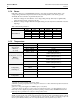
LCC/LCD2-14 Series Oven Owner’s Manual Version 1 PREFACE 2 Revision History—LCC/LCD2-14 Series Revision A B C D E F G H I J K L M 1 Date 7/2002 11/2002 8/2003 11/2003 3/2004 6/2004 8/2006 5/2007 7/2007 11/2007 9/2008 3/2009 3/2010 2/2013 Author Livingston Description Initial creation. Drawing changes, add line connection detail. Update drawings. Updated to Protocol Plus Version 4.0. Update drawings, change Class A warning. Change water drain/outlet temp rating. Update to current design.
LCC/LCD2-14 Series Oven Owner’s Manual Version 1 Table of Contents 1. About This Manual ............................................................................................................. 6 1.1. Important User Information ..................................................................................... 6 1.2. Manufacturer & Service .......................................................................................... 7 1.3. Organization of this Manual .....................................
LCC/LCD2-14 Series Oven Owner’s Manual Version 1 PREFACE 4 5. 6. 7. 8. 4.2.2.2. Air Atmosphere with Optional Water Cooling Model .................................. 26 4.2.3. Exhaust Connections ......................................................................................... 28 4.2.4. Wiring & Power Connections ........................................................................... 29 4.3. HEPA Filter Installation .............................................................................
LCC/LCD2-14 Series Oven Owner’s Manual Version 1 Figure 4. Protocol 3 Operator Interface. ........................................................................................ 18 Figure 5. This Side Up Graphic..................................................................................................... 19 Figure 6. Magnehelic Pressure Gauge Measures Pressure in Front of the HEPA Filter. .............. 21 Figure 7. LCC/LCD2-14 Series Optional Beacon Light. .........................................
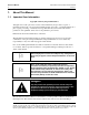
LCC/LCD2-14 Series Oven Owner’s Manual Version 1 ABOUT THIS MANUAL 6 1. About This Manual 1.1. Important User Information Copyright © 2013 by Despatch Industries. All rights reserved.
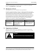
LCC/LCD2-14 Series Oven Owner’s Manual Version 1 ABOUT THIS MANUAL 7 maintaining Despatch Industries products. If any questions or problems arise, call Despatch Industries at 1-888-DESPATCH or 1-952-469-5424. 1.2. Manufacturer & Service The LCC/LCD2-14 Series oven is manufactured by Despatch Industries. Despatch has specialized in thermal processing for over 100 years.
LCC/LCD2-14 Series Oven Owner’s Manual Version 1 ABOUT THIS MANUAL 8 1.4. Conventions This icon signifies information that describes an unsafe condition that may result in death, serious injury, or damage to the equipment. Danger! Warning! Caution! Notice LOG OUT Danger is the signal word used to indicate a hazardous situation that, if not avoided, will result in death or severe injury.
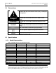
LCC/LCD2-14 Series Oven Owner’s Manual Version 1 ABOUT THIS MANUAL 9 1.5.2. Dimensions Models LCC/LCD2-14 Chamber Size inches (cm) * W D H 25.5 26 37 (64) (66) (94) Capacity 3 ft (liters) 14 (396) Overall Size inches (cm) W D H 47.5 41.5 71 (121) (105) (180) Maximum number of Shelves 11 The LCC/LCD2-14 oven is not intended to process solvents or other volatile or flammable materials. Oven forced exhaust is intended for cooling purposes only on standard and inert (nitrogen) models.
LCC/LCD2-14 Series Oven Owner’s Manual Version 1 ABOUT THIS MANUAL 10 1.5.4. Power If the line voltage for your LCC/LCD2-14 Series oven varies more than 10% from the oven voltage rating, electrical components such as relays and temperature controls may operate erratically. Power connection is performed by the user.
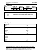
LCC/LCD2-14 Series Oven Owner’s Manual Version 1 Model ABOUT THIS MANUAL 11 LCC/LCD2-14 LCD 350°C LCC 50°C-260°C (air atmos.) 30°C-260°C (nitrogen atmos.) LCD 50°C-350°C (air atmos.) 30°C-350°C (nitrogen atmos.) Operating Range w/20°C Ambient Control Stability 1.5.6. ±0.5°C Capability The standard LCC/LCD2-14 Series oven is not available for Class A flammable solvent environments.
LCC/LCD2-14 Series Oven Owner’s Manual Version 1 SAFETY 12 2. Safety 2.1. Safety Information Do not work on the LCC/LCD2-14 Series oven without reading and understanding this section which contains important information and warnings. Ignoring these warnings can result in death, serious injury or damage to the machine and product. 2.1.1. Lockout Machine lockout places the LCC/LCD2-14 Series oven into a zero energy state and prevents accidental machine start up.
LCC/LCD2-14 Series Oven Owner’s Manual Version 1 without these safety devices in place creates hazards that the doors and covers are intended to render safe for personnel. The door requires a Manual Override Key for use when power is off. The door and panel that require a tool to open are part of the safety system of the LCC/LCD2-14 Series oven. Do not open the door while the machine is running. The LCC/LCD2-14 is also equipped with a door switch which turns off the heater when the door is opened. 2.2.
LCC/LCD2-14 Series Oven Owner’s Manual Version 1 SAFETY 14 2. De-energize the machine immediately by turning OFF the DISCONNECT SWITCH (if applicable). 3. Turn off the remote main disconnect (customer supplied disconnect). 4. Shut off fuel. 5. Call the fire department. 6. Stay away. Danger! Always disconnect all power before extinguishing a fire. Attempting to extinguish a fire in a machine connected to electrical power can result in serious injury or death. 2.5.
LCC/LCD2-14 Series Oven Owner’s Manual Version 1 2.5.2. Manual Unlock If a power failure occurs insert a torx tip tool (provided) and rotate 90 degrees counterclockwise to allow the chamber door to open. The tool must be turned back to the locked position to allow electrical operation again. To check door and latch for smooth operation, use a hollow point torx tip tool and rotate 90 degrees counterclockwise the manual override in the safety switch.
LCC/LCD2-14 Series Oven Owner’s Manual Version 1 THEORY OF OPERATION 16 3. Theory of Operation 3.1. The LCC/LCD2-14 Series Oven The LCC/LCD2-14 Series oven (Figure 3), a class 100 clean room oven, offers HEPA (High Efficiency Particulate Air) filtration for processes where minimized contamination is essential. Forced convected airflow provides rapid uniform distribution of heat. The removable HEPA filter is designed to provide a constant flow of 99.97% clean air to the product being heated.
LCC/LCD2-14 Series Oven Owner’s Manual Version 1 THEORY OF OPERATION 17 The LCC2-14 Series ovens have an electrical door lock that prevents the operator from opening the chamber door when a cycle is in process. The door lock is de-energized at the end of a cycle or when power is off. The nitrogen models have a Type 316 stainless steel water coil which permits rapid cool-down and lower temperature operation.
LCC/LCD2-14 Series Oven Owner’s Manual Version 1 THEORY OF OPERATION 18 3.2. The Protocol 3 Controller The Protocol 3 is a microprocessor based digital temperature controller designed for simple and flexible oven operation (Figure 4). The Protocol 3 controller operates as a dual-functioning controller/High Limit instrument. The control portion utilizes a time-proportioning voltage signal to control heating devices with minimal temperature fluctuations.
LCC/LCD2-14 Series Oven Owner’s Manual Version 1 THEORY OF OPERATION 19 LCC oven chamber temperature transitions must not exceed 1.5°C/minute to maintain class 100 chamber conditions. For ramp rates greater than 1.5°C/minute and up to 5°C/minute, the LCD model will maintain class 100 chamber conditions. 3.3.1. Definitions Binder: Organic substance used in filter construction to provide the media with structural strength. Burn-Off: Process for eliminating the binder contained in the filter. D.
LCC/LCD2-14 Series Oven Owner’s Manual Version 1 THEORY OF OPERATION 20 If an unpackaged HEPA filter unit must be placed with its face on the floor or other surface, clear the surface entirely of every object or irregularity which might damage the filter pack. 3.3.3.
LCC/LCD2-14 Series Oven Owner’s Manual Version 1 3.3.3.4. THEORY OF OPERATION 21 HEPA Filter Burn-off Process HEPA filters contain a binder material which protects the filter media during production and shipping. Smoke produced from burning this binder at elevated temperatures is undesirable during normal oven operation. Burning off the binder will ensure a clean process at elevated temperatures.
LCC/LCD2-14 Series Oven Owner’s Manual Version 1 THEORY OF OPERATION 22 3.4. Optional Beacon Light The LCC/LCD2-14 Series beacon light option provides visual cycle process indication to the operator (Figure 7). The beacon light option is on the front control panel of both the LCC/LCD2-14PT-3 Pass-Through oven and the standard LCC/LCD2-14 oven. The beacon light provides visual indication of the cycle status Figure 7. LCC/LCD2-14 Series Optional Beacon Light.
LCC/LCD2-14 Series Oven Owner’s Manual Version 1 4. ASSEMBLY & SETUP 23 Assembly & Setup Assembly and Setup provides directions for unpacking and installing your LCC/LCD2-14 Series oven. 4.1. Unpack & Inspect The LCC/LCD Oven Remove all packing materials and thoroughly inspect the oven for any damage that might have occurred during shipment. Note the condition of the carton and plastic cover sheet inside the carton. Observe all outside surfaces and corners of the oven for scratches and dents.
LCC/LCD2-14 Series Oven Owner’s Manual Version 1 ASSEMBLY & SETUP 24 Warning! Do not use the oven in wet, corrosive or explosive atmospheres unless this oven is specifically designed for a special atmosphere. 4.2.1.1. Oven Placement Requirements The LCC/LCD2-14 Series oven has a four inch diameter exhaust opening. The oven may be placed next to another cabinet on its right, or next to another oven, with three-quarters of an inch (19mm) clearance (measure with door open).
LCC/LCD2-14 Series Oven Owner’s Manual Version 1 ASSEMBLY & SETUP 25 Connection LCC/LCD Air Atmosphere models with optional water-cooling WATER DRAIN WATER INLET LCC/LCD Nitrogen Atmosphere models with standard water-cooling At the end of a cooling cycle, Nitrogen or Clean Dry Air is purged through the water coil. Water and pressurized nitrogen/air exit this connection for 30 seconds. Must be connected to gravity style drain (no backpressure).
LCC/LCD2-14 Series Oven Owner’s Manual Version 1 ASSEMBLY & SETUP 26 Water pressure supplied to the oven must not exceed 100 psi (6.89 bar). Despatch recommends installing a regulator to prevent surging. 3. Check for leaks by slowly opening the valve on the flowmeter and allowing any air to bleed out. Caution! Failure to allow air to bleed from the flowmeter may damage the flowmeter. Bleed air from the flowmeter after every instance of shutting off the water supply. 4.
LCC/LCD2-14 Series Oven Owner’s Manual Version 1 ASSEMBLY & SETUP 27 Water pressure supplied to the oven must not exceed 100 psi (6.9 bar). Despatch recommends installing a regulator to prevent surging. 2. Check for leaks by slowly opening the valve on the flowmeter and allowing any air to bleed out. Caution! Failure to allow air to bleed from the flowmeter may damage the flowmeter. Bleed air from the flowmeter after every instance of shutting off the water supply. 3.
LCC/LCD2-14 Series Oven Owner’s Manual Version 1 ASSEMBLY & SETUP 28 4.2.3. Exhaust Connections The LCC/LCD2-14 Series oven exhaust port is located on the rear of the oven (Figure 9). Table 4 lists the requirements for the exhaust stack for the LCC/LCD2-14 Series oven. Cooling Fan Exhaust Opening Figure 9. Exhaust Connections. Notice Do not cover cabinet cooling fan. The cooling fan is required for lower compartment ventilation.
LCC/LCD2-14 Series Oven Owner’s Manual Version 1 ASSEMBLY & SETUP 29 4.2.4. Wiring & Power Connections Danger! Contact with energized electrical sources may result in serious injury or death. All wiring to be completed by properly trained and licensed personnel. The oven must be hardwired directly to the disconnect switch on the equipment panel (Figure 11). Danger! All grounding and safety equipment must be in compliance with applicable codes, ordinances and accepted safe practices.
ASSEMBLY & SETUP 30 LCC/LCD2-14 Series Oven Owner’s Manual Version 1 Connect Power to Disconnect Switch Labeled Line Connections Power Conduit from Rear of Oven Figure 11. Conduit and Disconnect Switch/Line Connections. Copyright © 2013 by Despatch Industries. All rights reserved.
LCC/LCD2-14 Series Oven Owner’s Manual Version 1 ASSEMBLY & SETUP 31 4.3. HEPA Filter Installation Not all LCC/LCD2-14 ovens come equipped with a HEPA filter. This HEPA filter installation section applies only to ovens designed for ISO Class 5 (Class 100) use, which are equipped with a HEPA filter. For a complete explanation of model numbers, refer to Section 1.5.1. Two different types of filters are typically used.
LCC/LCD2-14 Series Oven Owner’s Manual Version 1 ASSEMBLY & SETUP 32 4.3.1. HEPA Filter Handling and Inspection 1. Remove new filter from carton Notice Sweep floor clear of nuts, bolts and other protrusions which may damage the unit. Do not drop or jar the filter carton. Do not attempt to repair the damaged filter unit—particularly the medium. Any unit so repaired must be retested to assure that hidden damage does not exist which might reduce filtering efficiency.
LCC/LCD2-14 Series Oven Owner’s Manual Version 1 ASSEMBLY & SETUP 33 Opened pleats in the filter media are normal and result from the tempering process. 3. Pull shelves from the oven and set aside. Danger! Make certain power is disconnected from the oven before removing or replacing the HEPA filter. Loosen screws to remove the entire inner casing assembly as a single unit. Figure 13. LCC/LCD2-14 Side Panel. 4.
LCC/LCD2-14 Series Oven Owner’s Manual Version 1 ASSEMBLY & SETUP 34 b. Discard the old filter in accordance with your company’s disposal policies. c. Remove and discard the conduit spacers from the rods behind the filter frame. 6. Place the new filter in the oven: a. For the High-temperature HEPA filter: i. Place the filter with the triangular gasket set against the oven wall and the glass braid set against the clamping plate (Figure 14). ii.
LCC/LCD2-14 Series Oven Owner’s Manual Version 1 ASSEMBLY & SETUP 35 Figure 15. Install HEPA standard filter. 7. Reinstall filter frame using the nuts removed earlier. a. Make sure the filter face is tight against the inside perimeter of the frame on all sides. 8. Reinstall the brass nuts and washers to tighten the filter frame down. a. Tighten the nuts alternately for even tightness. i. Be careful not to over tighten. Correct installation torque is 28 +/- 3 in-lbs (3.16 ± .33 N-m). ii.
LCC/LCD2-14 Series Oven Owner’s Manual Version 1 ASSEMBLY & SETUP 36 4.3.2. HEPA Filter Burn-Off 4.3.2.1. HEPA Filter Burn-Off Process The burn-off process takes place in any equipment where a new HEPA filter is used at temperatures above 180°C (356°F). Expect smoke, possibly a pungent odor and a light residue on interior surfaces. This results from oxidation of the binder. Most of the binder will leave the filter after running at a temperature of 260°C (500°F) for 48 hours.
LCC/LCD2-14 Series Oven Owner’s Manual Version 1 ASSEMBLY & SETUP 37 a. Use enough fresh air to remove the smoke, while still being able to achieve and maintain the necessary temperature. b. The completion of the burn-off period should be based on the particle level in the oven or smoke-free exhaust and minimal odor level. c. Check the filter hold-down nuts after burn-off and tighten as necessary. d. For best oven particle control, this step should be repeated on a regular basis.
LCC/LCD2-14 Series Oven Owner’s Manual Version 1 OPERATION 38 5. Operation Users and operators of this oven must comply with operating procedures and training of operating personnel as required by the Occupational Safety and Health Act (OSHA) of 1970, Section 5 and relevant safety standards, and other safety rules and regulations of state and local governments. Refer to the relevant safety standards in OSHA and National Fire Protection Association (NFPA), Section 86 of 1990.
LCC/LCD2-14 Series Oven Owner’s Manual Version 1 OPERATION 39 The two shelves are designed to be pulled out about halfway without tipping. Do not overload the shelves. Distribute the workload evenly so airflow is not restricted. Do not overfill your oven. The workload should not take up more than two-thirds of any dimension of the inside cavity. 5.2. Pre-Startup Checklist □ □ □ Know the system. Read this manual carefully. Make use of its instructions and explanations.
LCC/LCD2-14 Series Oven Owner’s Manual Version 1 OPERATION 40 5.3. Operating Procedure 5.3.1. Start The LCC/LCD2-14 Oven 1. Turn the yellow/red DISCONNECT SWITCH to ON (Figure 17). 2. Press the POWER for ON. a. The door remains unlocked. During the process cycle the door is locked. To unlock the door press STOP or remove power from oven using the DISCONNECT SWITCH.
LCC/LCD2-14 Series Oven Owner’s Manual Version 1 OPERATION 41 5.3.2. LCC/LCD2-14 Class A Oven Operation 1. 2. 3. 4. 5. 6. Verify the purge time with the time listed on the nameplate (Figure 18). Turn the yellow/red DISCONNECT SWITCH to ON (Figure 17). Press the POWER for ON. Close the main disconnect switch. Press the START push button. Start the profile. The exhaust fan will start, the airflow switch will actuate, and the purge timer will begin timing. 7.
LCC/LCD2-14 Series Oven Owner’s Manual Version 1 OPERATION 42 a. The oven should be idle, empty, with the door closed and awaiting the next lot for processing. b. The Protocol 3 Controller should not be running a profile. 2. Open the oven door. The amber beacon light (Error! Reference source not found.) ill be ON (steady) until the profile is started (at the completion of Step 5). 3. Place the product on the shelf in the oven. 4. Close the oven door. 5.
LCC/LCD2-14 Series Oven Owner’s Manual Version 1 OPERATION 43 5.3.5. Sequence of Operation for Ovens Equipped for LCC/LCD2-14 Inert Atmosphere Oven Danger! Suffocation can occur in a nitrogen-atmosphere oven chamber if it is not thoroughly purged with room air before a person goes inside it. Before entering an oven chamber run the oven for at least five minutes with the nitrogen (or any other inert gas) turned off, doors open and recirculation fan running.
LCC/LCD2-14 Series Oven Owner’s Manual Version 1 OPERATION 44 Figure 20. Adjust Nitrogen needle valve (in compartment beneath oven). 10. The third and final segment is the COOLDOWN MODE. In Cooldown mode, water valves are energized to bring the chamber to a safe unloading temperature. a. Set water cooling flow meter to 3 GPM (11 LPM), and adjust if necessary. b. Water cooling flowmeter is located on the lower left side of the oven. 5.3.6. Main Disconnect and Manual Unlock 5.3.6.1.
LCC/LCD2-14 Series Oven Owner’s Manual Version 1 5.3.6.2. OPERATION 45 Manual Unlock If a power failure occurs insert a torx tip tool (provided) and rotate 90 degrees counterclockwise to allow the chamber door to open. The tool must be turned back to the locked position to allow electrical operation again. Warning! The LCC/LCD2-14 door requires a Manual Override Key for use when power is OFF. The door and panel that require a tool to open are part of the safety system of the LCC/LCD2-14 Oven.
LCC/LCD2-14 Series Oven Owner’s Manual Version 1 MAINTENANCE 46 6. Maintenance Do not attempt any service on this oven before opening the main power disconnect switch. Danger! Disconnect all power sources before making repairs. Contact with energized electrical sources may result in serious injury or death. 6.1. Checklist Keep equipment clean. Gradual dirt accumulation retards airflow.
LCC/LCD2-14 Series Oven Owner’s Manual Version 1 MAINTENANCE 47 6.2. Maintenance Schedule Preventive Maintenance (Refer to Section) Daily Weekly Monthly Every Three Months Every Six Months Annually As Needed General Avoid placing load too close to supply duct (5.1) Visually inspect for dirt, debris and free movement of parts and controls. X X Clean as needed Inspect door seals for proper seating, damage and/or tears Inspect door operation.
LCC/LCD2-14 Series Oven Owner’s Manual Version 1 MAINTENANCE 48 6.3. Lubrication Fan motor bearings are permanently lubricated. All door latches, hinges, door operating mechanisms, bearing or wear surfaces should be lubricated to ensure easy operation. 6.4. HEPA Filter Replacement Refer to Section 4.3 for filter replacement. 6.4.1. Routine HEPA Filter Inspection Section 4.3.1 provides more detail about HEPA filter handling and inspection prior to installation. 1.
LCC/LCD2-14 Series Oven Owner’s Manual Version 1 MAINTENANCE 49 6.5.2. Decontaminating the LCC2-14 Series Oven Warning! Do not decontaminate oven without first disconnecting power. Ensure adequate personal safety while decontaminating oven. Notice Before using any cleaning or decontamination method except those recommended by the manufacturer, users should check with the manufacturer that the proposed method will not damage the equipment. For best results, decontaminate the work zone daily. 1.
TROUBLESHOOTING 50 7. LCC/LCD2-14 Series Oven Owner’s Manual Version 1 Troubleshooting: Error Messages and Alarm Table 5 lists the more common error messages, possible problems and remedies. Table 5. Error Messages and Next Steps.
LCC/LCD2-14 Series Oven Owner’s Manual Version 1 8. APPENDICES 51 Appendices 8.1. HEPA Filter Pressure Reading Worksheet Table 6. HEPA Filter Pressure Reading Worksheet. A B C D Date Comments Pressure Pressure with 350 (inches of SCFH nitrogen water) purge Typical 2-3” 1.5-2.5” above value Values in Column C Filter first installed E Pressure with 220 SCFH nitrogen maintain 0.3-0.8” above value in Column C F Oven Temperature 60°C Copyright © 2013 by Despatch Industries. All rights reserved.
LCC/LCD2-14 Series Oven Owner’s Manual Version 1 APPENDICES 52 8.2. LCC/LCD2-14 Series Oven Options 8.2.1. Optional MRC5000 Setup Refer to instructions provided recorder manufacturer for more specific installation notes. Temperature is retransmitted to the MRC5000 recorder from the controller. To set up the recorder: 1. Ensure hardware jumper JU1 is in place for the 5 VDC setting (Refer to MRC5000 Manual included). 2. Move MODE to PROG/TEST/CAL to display Prog. 3. Press ▼ twice to display Inps.
LCC/LCD2-14 Series Oven Owner’s Manual Version 1 APPENDICES 53 When the chamber temperature exceeds the High Limit setting on the control, the heater shuts down, the alarm horn sounds and the red push button switch will illuminate. To silence the alarm: 1. Depress the Alarm Silence switch (Figure 23). a. This silences the alarm horn. b. The red push button switch remains illuminated.
LCC/LCD2-14 Series Oven Owner’s Manual Version 1 APPENDICES 54 8.3. Standard Products Warranty 8.4. Electrical Schematics The following pages contain electrical schematics for the LCC/LCD2-14 Series oven. Copyright © 2013 by Despatch Industries. All rights reserved.
LCC/LCD2-14 Series Oven Owner’s Manual Version 1 APPENDICES 55 Figure 24. LCC/LCD2-14 (Drawing 320905-01). Copyright © 2013 by Despatch Industries. All rights reserved. No part of the contents of this manual may be reproduced, copied or transmitted in any form or by any means including graphic, electronic, or mechanical methods or photocopying, recording, or information storage and retrieval systems without the written permission of Despatch Industries, unless for purchaser's personal use.
LCC/LCD2-14Series Oven Owner’s Manual Version 1 APPENDICES 56 Figure 25. LCC/LCD2-14 (Drawing 320905-02). Copyright © 2013 by Despatch Industries. All rights reserved. No part of the contents of this manual may be reproduced, copied or transmitted in any form or by any means including graphic, electronic, or mechanical methods or photocopying, recording, or information storage and retrieval systems without the written permission of Despatch Industries, unless for purchaser's personal use.
LCC/LCD2-14 Series Oven Owner’s Manual Version 1 APPENDICES 57 Figure 26. LCC/LCD2-14 (Drawing 320905-03). Copyright © 2013 by Despatch Industries. All rights reserved. No part of the contents of this manual may be reproduced, copied or transmitted in any form or by any means including graphic, electronic, or mechanical methods or photocopying, recording, or information storage and retrieval systems without the written permission of Despatch Industries, unless for purchaser's personal use.
LCC/LCD2-14Series Oven Owner’s Manual Version 1 APPENDICES 58 Figure 27. LCC/LCD2-14 (Drawing 320905-04). Copyright © 2013 by Despatch Industries. All rights reserved. No part of the contents of this manual may be reproduced, copied or transmitted in any form or by any means including graphic, electronic, or mechanical methods or photocopying, recording, or information storage and retrieval systems without the written permission of Despatch Industries, unless for purchaser's personal use.
LCC/LCD2-14 Series Oven Owner’s Manual Version 1 59 3rdDraft— Copyright © 2013 by Despatch Industries. All rights reserved. No part of the contents of this manual may be reproduced, copied or transmitted in any form or by any means including graphic, electronic, or mechanical methods or photocopying, recording, or information storage and retrieval systems without the written permission of Despatch Industries, unless for purchaser's personal use.