
User Manual


Table Of Contents
- Revision History
- Table of Contents
- Figures
- Tables
- 1. About This Manual
- Copyright © 2012 by Despatch Industries.
- Printed and bound in the United States of America.
- Table 1. Operating/Environmental Conditions (For indoor use).
- 2. Safety
- 2.1. Safety Information
- 2.1.1. Lockout
- 2.1.1.1. Lockout Requirements
- 2.1.1.2. Lockout Procedure
- 2.2. Provisions for Lifting and Carrying
- 2.3. Maintenance
- 2.4. Electrical Power
- 2.5. Fire
- 2.6. Equipment Lockout Requirements
- 2.6.1. Emergency Stop
- 2.7. Disconnecting Devices
- 2.7.1. Power Requirements
- 2.7.2. Disconnecting Hard-Wired Units
- 2.7.3. Disconnecting Corded Units
- 2.7.4. Disconnecting Units with Optional Disconnect Switch
- 3. Theory of Operation
- Table 2. Control Instrument Explanations.
- Review the Protocol 3 Controller Owner’s Manual for more information.
- Table 3. High Limit Instrument Explanations.
- 4. Assembly & Setup
- 5. Operation
- Table 4. Control Instrument Operating Parameters.
- Table 5. Control Instrument Set-up Parameters.
- Refer to Table 5 to change tuning parameters, if necessary.
- Table 6. High Limit instrument Setup Parameters.
- 6. Maintenance
- 6.1. Checklist
- 6.2. Lubrication
- 6.3. Cleaning and Decontamination
- 6.3.1. Cleaning the LBB Series Oven
- 6.3.2. Decontaminating the LBB Series Oven
- 6.4. Routine Tests
- 6.4.1. Test Control Instrument
- 6.4.2. Test High Limit Instrument
- 6.5. Replacement Parts
- 6.5.1. Replace the Control Instrument
- 6.5.2. Replace High Limit Instrument
- 6.5.3. Replace (Optional) Protocol 3 Controller
- 6.5.4. Replace Heater Unit
- 6.5.5. Replace Fan Motor
- 7. Troubleshooting
- Table 7. Common Technical Issues and Remedies.
- 8. Appendices
- Each oven schematic (Section 0) shows the wiring for this option.
- Each oven schematic (Section 8.4) shows the wiring for this option.
- Each oven schematic (Section 0) shows the wiring for this option.
- Table 8. LBB1-23A-1 Parts.
- Table 9. LBB1-23B-1 Parts.
- Table 10. LBB1-43A-1 Parts.
- Table 11. LBB1-43B-1 Parts.
- Table 12. LBB1-69A-1 Parts.
- Table 13. LBB1-69B-1 Parts.
- Table 14. LBB2-12-1 Parts.
- Table 15. LBB2-18-1 Parts.
- Table 16. LBB2-27-1 Parts.
LBB Series Oven Owner’s Manual APPENDICES
Version 15 57
Copyright © 2012 by Despatch Industries.
All rights reserved. No part of the contents of this manual may be reproduced, copied or transmitted in any form or by any
means including graphic, electronic, or mechanical methods or photocopying, recording, or information storage and
retrieval systems without the written permission of Despatch Industries, unless for purchaser's personal use.
8.2. Optional Equipment
8.2.1. Assemble Oven Stand
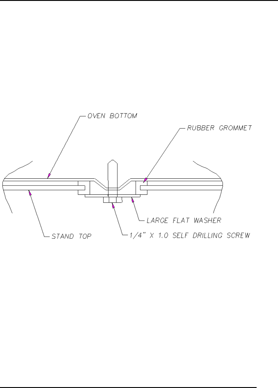
1. Install four rubber grommets into holes in the stand (Figure 25).
a. For LBB1-69 stands, the rear grommets mount into the forward set of rear holes.
b. On LBB2-12 stands the rear grommets mount into the set of holes closest to the rear
of the stand.
2. Place the oven on top of the stand. The four embossed areas in the bottom of the oven should
center in the grommets.
3. Using the self-drilling screw and large flat washer provided, install through each embossed
area as shown below.
Figure 25. Optional LBB Oven Stand.