
User Manual


Table Of Contents
- Revision History
- Table of Contents
- Figures
- Tables
- 1. About This Manual
- Copyright © 2012 by Despatch Industries.
- Printed and bound in the United States of America.
- Table 1. Operating/Environmental Conditions (For indoor use).
- 2. Safety
- 2.1. Safety Information
- 2.1.1. Lockout
- 2.1.1.1. Lockout Requirements
- 2.1.1.2. Lockout Procedure
- 2.2. Provisions for Lifting and Carrying
- 2.3. Maintenance
- 2.4. Electrical Power
- 2.5. Fire
- 2.6. Equipment Lockout Requirements
- 2.6.1. Emergency Stop
- 2.7. Disconnecting Devices
- 2.7.1. Power Requirements
- 2.7.2. Disconnecting Hard-Wired Units
- 2.7.3. Disconnecting Corded Units
- 2.7.4. Disconnecting Units with Optional Disconnect Switch
- 3. Theory of Operation
- Table 2. Control Instrument Explanations.
- Review the Protocol 3 Controller Owner’s Manual for more information.
- Table 3. High Limit Instrument Explanations.
- 4. Assembly & Setup
- 5. Operation
- Table 4. Control Instrument Operating Parameters.
- Table 5. Control Instrument Set-up Parameters.
- Refer to Table 5 to change tuning parameters, if necessary.
- Table 6. High Limit instrument Setup Parameters.
- 6. Maintenance
- 6.1. Checklist
- 6.2. Lubrication
- 6.3. Cleaning and Decontamination
- 6.3.1. Cleaning the LBB Series Oven
- 6.3.2. Decontaminating the LBB Series Oven
- 6.4. Routine Tests
- 6.4.1. Test Control Instrument
- 6.4.2. Test High Limit Instrument
- 6.5. Replacement Parts
- 6.5.1. Replace the Control Instrument
- 6.5.2. Replace High Limit Instrument
- 6.5.3. Replace (Optional) Protocol 3 Controller
- 6.5.4. Replace Heater Unit
- 6.5.5. Replace Fan Motor
- 7. Troubleshooting
- Table 7. Common Technical Issues and Remedies.
- 8. Appendices
- Each oven schematic (Section 0) shows the wiring for this option.
- Each oven schematic (Section 8.4) shows the wiring for this option.
- Each oven schematic (Section 0) shows the wiring for this option.
- Table 8. LBB1-23A-1 Parts.
- Table 9. LBB1-23B-1 Parts.
- Table 10. LBB1-43A-1 Parts.
- Table 11. LBB1-43B-1 Parts.
- Table 12. LBB1-69A-1 Parts.
- Table 13. LBB1-69B-1 Parts.
- Table 14. LBB2-12-1 Parts.
- Table 15. LBB2-18-1 Parts.
- Table 16. LBB2-27-1 Parts.
OPERATION LBB Series Oven Owner’s Manual
34 Version 15
Copyright © 2012 by Despatch Industries.
All rights reserved. No part of the contents of this manual may be reproduced, copied or transmitted in any form or by any
means including graphic, electronic, or mechanical methods or photocopying, recording, or information storage and
retrieval systems without the written permission of Despatch Industries, unless for purchaser's personal use.
5.4.2. Control Instrument Parameter Programming Mode
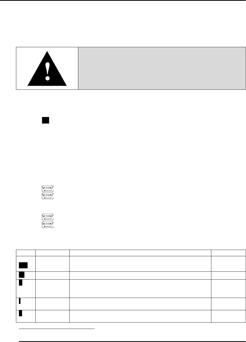
Warning!
Changing program parameters alters the function of the Control.
Proceed carefully and fully understand each parameter before
changing that parameter.
Control instrument parameters are set through the Operating and Set-up modes. In most
applications, it is not necessary to alter the oven settings. The following instructions describe how
to access, view and if desired, change the parameters. Once the Operating and Set-up modes are
accessed, SP will start blinking on and off. Table 4 and Table 5 explain the Operating and Set-up
Mode parameters.
The Control Instrument will not allow the display to be altered improperly. The Control
Instrument will automatically exit the Parameter Programming mode if no keys are pressed for
about two (2) minutes.
5.4.2.1. Entering Control Instrument Operating and Set-up Mode
To enter the Operating and Set-up Mode (Figure 4):
1. Press for three (3) seconds.
2. Press until the desired parameter displays. See Table 4 for more information.
3. Press ▲ or ▼ to display the value.
4. Use ▲ or ▼ to move to the desired setting.
5. Press to enter the value.
6. Press and hold for three (3) seconds to return to the display mode.
Table 4. Control Instrument Operating Parameters.
Code
Name
Description
Settings
CtL
Control
Mode
Determines whether controller functions as a time
proportional or an on/off control.
PID
At
Auto-tuning
OFF for PID tuning, ON for controller to tune process
OFF
P
Proportional
Band
Expressed in degrees, value determines the band width
on both sides of the setpoint within which the control
provides proportional control.
4
(8 if F)
4
I
Integral
Time
Expressed in seconds, value corrects for errors in actual
temperature versus the setpoint
15
d
Derivative
Time
Expressed in seconds, value shows the effect of the
derivative time is in direct proportion to the time setting
0
4
If P is not displayed the Control Mode (CtL) must be first set to PID.