
User Manual


Table Of Contents
- Revision History
- Table of Contents
- Figures
- Tables
- 1. About This Manual
- Copyright © 2012 by Despatch Industries.
- Printed and bound in the United States of America.
- Table 1. Operating/Environmental Conditions (For indoor use).
- 2. Safety
- 2.1. Safety Information
- 2.1.1. Lockout
- 2.1.1.1. Lockout Requirements
- 2.1.1.2. Lockout Procedure
- 2.2. Provisions for Lifting and Carrying
- 2.3. Maintenance
- 2.4. Electrical Power
- 2.5. Fire
- 2.6. Equipment Lockout Requirements
- 2.6.1. Emergency Stop
- 2.7. Disconnecting Devices
- 2.7.1. Power Requirements
- 2.7.2. Disconnecting Hard-Wired Units
- 2.7.3. Disconnecting Corded Units
- 2.7.4. Disconnecting Units with Optional Disconnect Switch
- 3. Theory of Operation
- Table 2. Control Instrument Explanations.
- Review the Protocol 3 Controller Owner’s Manual for more information.
- Table 3. High Limit Instrument Explanations.
- 4. Assembly & Setup
- 5. Operation
- Table 4. Control Instrument Operating Parameters.
- Table 5. Control Instrument Set-up Parameters.
- Refer to Table 5 to change tuning parameters, if necessary.
- Table 6. High Limit instrument Setup Parameters.
- 6. Maintenance
- 6.1. Checklist
- 6.2. Lubrication
- 6.3. Cleaning and Decontamination
- 6.3.1. Cleaning the LBB Series Oven
- 6.3.2. Decontaminating the LBB Series Oven
- 6.4. Routine Tests
- 6.4.1. Test Control Instrument
- 6.4.2. Test High Limit Instrument
- 6.5. Replacement Parts
- 6.5.1. Replace the Control Instrument
- 6.5.2. Replace High Limit Instrument
- 6.5.3. Replace (Optional) Protocol 3 Controller
- 6.5.4. Replace Heater Unit
- 6.5.5. Replace Fan Motor
- 7. Troubleshooting
- Table 7. Common Technical Issues and Remedies.
- 8. Appendices
- Each oven schematic (Section 0) shows the wiring for this option.
- Each oven schematic (Section 8.4) shows the wiring for this option.
- Each oven schematic (Section 0) shows the wiring for this option.
- Table 8. LBB1-23A-1 Parts.
- Table 9. LBB1-23B-1 Parts.
- Table 10. LBB1-43A-1 Parts.
- Table 11. LBB1-43B-1 Parts.
- Table 12. LBB1-69A-1 Parts.
- Table 13. LBB1-69B-1 Parts.
- Table 14. LBB2-12-1 Parts.
- Table 15. LBB2-18-1 Parts.
- Table 16. LBB2-27-1 Parts.
LBB Series Oven Owner’s Manual THEORY OF OPERATION
Version 15 23
Copyright © 2012 by Despatch Industries.
All rights reserved. No part of the contents of this manual may be reproduced, copied or transmitted in any form or by any
means including graphic, electronic, or mechanical methods or photocopying, recording, or information storage and
retrieval systems without the written permission of Despatch Industries, unless for purchaser's personal use.
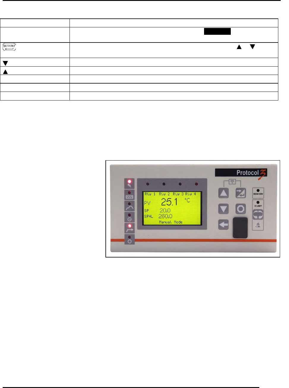
Figure 5. Protocol 3 Operator Interface.
Table 2. Control Instrument Explanations.
3.3. The Protocol 3 Controller
The Protocol 3™ controller is a microprocessor based digital temperature controller designed for
simple and flexible oven operation (Figure 5). The Protocol 3 controller operates as a dual-
functioning controller/High Limit instrument. The control portion utilizes a time proportioning
voltage signal to control heating devices with minimal temperature fluctuations.
The High Limit portion protects the
product and/or the oven from
overheating. If the product being
processed has a critical high
temperature limit, the High Limit
setpoint should be set to a
temperature somewhat below the
temperature at which the product
could be damaged. If the product
does not have a critical high
temperature limit, the High Limit
setpoint should be set 5 to 15 degrees
higher than the maximum
programmed setpoint at which the oven
will operate.
The Protocol 3 controller provides three primary operating modes:
Manual: Oven operates continuously at a fixed temperature until turned off.
Timer: Oven operates at a fixed temperature for a user-selected time period, and then
automatically turns off.
Profile: Temperatures increase or decrease as defined by 255 segments that can be allocated
to 64 ramp and soak profiles. The profiles can be linked to provide additional temperature
combinations.
Review the Protocol 3 Controller Owner’s Manual for more information.
Display
Description
Main (PV) Display
Typically displays actual oven temperature. Press SET/ENT to display
setpoint. Displays parameter code and value.
Key
Press to switch between PV and SP displays. Enter data using or . Press
repeatedly to switches through parameter displays.
Decrease setpoint or mode parameter
Increase setpoint or mode parameter
SP
Lit when setpoint value displays
OUT
Lit when control calls for heat
AL1 –2
N/A