
User Manual


Table Of Contents
- Revision History
- Table of Contents
- Figures
- Tables
- 1. About This Manual
- Copyright © 2012 by Despatch Industries.
- Printed and bound in the United States of America.
- Table 1. Operating/Environmental Conditions (For indoor use).
- 2. Safety
- 2.1. Safety Information
- 2.1.1. Lockout
- 2.1.1.1. Lockout Requirements
- 2.1.1.2. Lockout Procedure
- 2.2. Provisions for Lifting and Carrying
- 2.3. Maintenance
- 2.4. Electrical Power
- 2.5. Fire
- 2.6. Equipment Lockout Requirements
- 2.6.1. Emergency Stop
- 2.7. Disconnecting Devices
- 2.7.1. Power Requirements
- 2.7.2. Disconnecting Hard-Wired Units
- 2.7.3. Disconnecting Corded Units
- 2.7.4. Disconnecting Units with Optional Disconnect Switch
- 3. Theory of Operation
- Table 2. Control Instrument Explanations.
- Review the Protocol 3 Controller Owner’s Manual for more information.
- Table 3. High Limit Instrument Explanations.
- 4. Assembly & Setup
- 5. Operation
- Table 4. Control Instrument Operating Parameters.
- Table 5. Control Instrument Set-up Parameters.
- Refer to Table 5 to change tuning parameters, if necessary.
- Table 6. High Limit instrument Setup Parameters.
- 6. Maintenance
- 6.1. Checklist
- 6.2. Lubrication
- 6.3. Cleaning and Decontamination
- 6.3.1. Cleaning the LBB Series Oven
- 6.3.2. Decontaminating the LBB Series Oven
- 6.4. Routine Tests
- 6.4.1. Test Control Instrument
- 6.4.2. Test High Limit Instrument
- 6.5. Replacement Parts
- 6.5.1. Replace the Control Instrument
- 6.5.2. Replace High Limit Instrument
- 6.5.3. Replace (Optional) Protocol 3 Controller
- 6.5.4. Replace Heater Unit
- 6.5.5. Replace Fan Motor
- 7. Troubleshooting
- Table 7. Common Technical Issues and Remedies.
- 8. Appendices
- Each oven schematic (Section 0) shows the wiring for this option.
- Each oven schematic (Section 8.4) shows the wiring for this option.
- Each oven schematic (Section 0) shows the wiring for this option.
- Table 8. LBB1-23A-1 Parts.
- Table 9. LBB1-23B-1 Parts.
- Table 10. LBB1-43A-1 Parts.
- Table 11. LBB1-43B-1 Parts.
- Table 12. LBB1-69A-1 Parts.
- Table 13. LBB1-69B-1 Parts.
- Table 14. LBB2-12-1 Parts.
- Table 15. LBB2-18-1 Parts.
- Table 16. LBB2-27-1 Parts.
THEORY OF OPERATION LBB Series Oven Owner’s Manual
22 Version 15
Copyright © 2012 by Despatch Industries.
All rights reserved. No part of the contents of this manual may be reproduced, copied or transmitted in any form or by any
means including graphic, electronic, or mechanical methods or photocopying, recording, or information storage and
retrieval systems without the written permission of Despatch Industries, unless for purchaser's personal use.
3.1.1. Oven Theory
The LBB Series forced circulating oven uses fan to circulate air through the chamber. A
circulating oven is much more efficient and uniform oven than a gravity-convection oven due to
the constant air movement. Soaking at a desired setpoint still depends on a number of parameters
including chamber area, load mass, the ability to absorb heat and the exhaust rate. But soak times
with a forced circulating oven may be shortened.
The LBB Series oven is capable of heating to 204°C (400°F). The oven uses a
microprocessor-based digital control to display the actual chamber temperature at the sensing
point. The temperature sensor is located to optimize control action for the entire chamber for
various load conditions. The control display may fluctuate a few degrees around the setpoint,
reflecting temperature changes at the sensor location. However, overall chamber temperature
remains stable. The strategic location of the sensor compensates for delays in heat convection and
enhances the performance and temperature control of the oven. The oven has been designed for
an overall result of quality productivity where fast processing and versatility are critical.
3.2. Control Systems
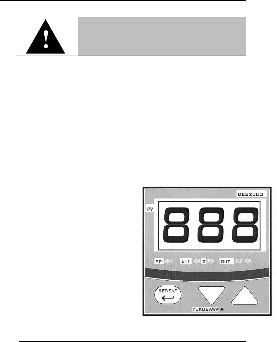
3.2.1. Primary Control Instrument
The LBB Series oven is equipped with a
microprocessor-based digital control instrument
configured as a proportional controller and set to
its optimum operating values (Figure 4). Initially
the control instrument allows the heater to operate
at full power. As the actual oven temperature
reaches the setpoint, the control instrument cycles
the heater on and off, minimizing process
temperature fluctuations. Table 2 provides
explanation for working with the control
instrument.
Warning!
Do not remove the hat bracket as it distributes exhaust air and
protects the exhaust opening from being completely covered.
Figure 4. LBB Series Oven Primary Control Instrument