
Manual


5
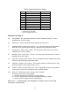
Table 2 Operating Parameter Outline
Code
Name
Settings
CtL
Control Mode
PID
At
Auto-tuning
OFF
P *
Proportional Band
5 **
I
Integral Time
120
d
Derivative Time
0
Ct
Cycle Time
1
FL
Input Filter
2
bS
PV Bias (Offset)
0
LoC
Key Lock
0
* If P is not displayed the Control Mode (CtL)
must be first set to Pid.
** For F change to value 13.
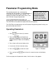
Definitions for Table 2:
CtL Control Mode - This parameter determines whether controller functions as a time
proportional or an on/off control.
At Auto-tuning – Off for PID tuning, ON for controller to tune process.
P Proportional Band - Expressed in degrees. This value determines the band width on
both sides of the setpoint within which the control provides proportional control.
I Integral Time - Expressed in seconds. This parameter corrects for errors in actual
temperature versus the setpoint.
D Derivative Time - Expressed in seconds. This effect of the derivative time is in direct
proportion to the time setting.
Ct Cycle Time - Expressed in seconds. This is the total time for one ON/OFF cycle of the
controller output during the proportional action.
FL Input Filter – Expressed in seconds. This function should be used when the PV may
fluctuate greatly (i.e. input signal contains noise).
bS PV Bias - Expressed in percent of span. From –100 to 100% of span, this parameter
used to set the actual oven temperature to the controller display.
LoC Key Lock - This provides levels of access to the controller.
0 = No key lock, full access to controller.
1 = Prevents changing of all parameters except setpoint.
2 = Prevents all parameters from being changed including the setpoint.
–1 = Set to enter the Setup parameter setting display.
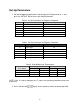
When LoC = -1, the parameters are displayed in the order shown in the Set-Up
Parameters section, below.