DES2000 CONTROL INSTRUCTION MANUAL C-191 PN 208712 REVISION B 12/2002
NOTICE Users of this equipment must comply with operating procedures and training of operation personnel as required by the Occupational Safety and Health Act (OSHA) of 1970, Section 6 and relevant safety standards, as well as other safety rules and regulations of state and local governments. Refer to the relevant safety standards in OSHA and National Fire Protection Association (NFPA), section 86 of 1990.
i
ii
TABLE OF CONTENTS INTRODUCTION ............................................................................................................. 1 OPERATION ................................................................................................................... 3 Parameter Programming Mode ................................................................................... 4 Changing Display From °C To °F ................................................................................
iv
INTRODUCTION The features of the DES2000 controller include: PID Tuning Display can show process variable or setpoint during normal operation Solid state output to operate a solid state relay The DES2000 controller is a microprocessor-based digital control instrument. The instrument can be configured as a proportional controller. Initially the CONTROL will allow the heater to operate at full power.
Figure 2.
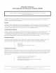
OPERATION For fastest oven heat-up time, close the exhaust vent. After the desired temperature is reached, the vent may be adjusted as needed. 1. Start oven. a. Turn POWER switch to on. Figure 3. Typical Control Panel 2. Enter setpoint on the CONTROL instrument. a. Press key until the SP LED is lit. b. Use ▲ key and ▼ key to set operating temperature. c. Press key to enter setpoint. d. Press key again to display process temperature.
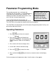
Parameter Programming Mode The control parameters are set through the Operating and Set-up modes. In most applications, it is not necessary to alter the oven settings. The following instructions describe how to access, view and, if desired, change the parameters. WARNING: Make sure you understand what you are changing before doing so. Changing the program parameters will alter the functions of the CONTROL. Once the Operating and Set-up modes are accessed, the SP LED will start blinking on and off.
Table 2 Operating Parameter Outline Code Name Settings CtL Control Mode PID At Auto-tuning OFF P* Proportional Band 5 ** I Integral Time 120 d Derivative Time 0 Ct Cycle Time 1 FL Input Filter 2 bS PV Bias (Offset) 0 LoC Key Lock 0 * If P is not displayed the Control Mode (CtL) must be first set to Pid. ** For F change to value 13. Definitions for Table 2: CtL Control Mode - This parameter determines whether controller functions as a time proportional or an on/off control.
Set-Up Parameters 1. Go into the operating parameters and change the LOC parameter to –1 and press the SET/ENT key to access the Setup Parameters.
Definitions for Tables 3 and 4: In Input Type - See Input Range Codes (Table 6) SPH Setpoint High - This should be set to the maximum operating temperature of the equipment. SPL Setpoint Low - This is the minimum operating temperature of the equipment.
Changing Display From °C To °F The control can be configured for either °C or °F. Use the following steps to change control from displaying °C to °F. WARNING: Make sure you understand what 1. Press and hold the for three (3) seconds. you are changing before doing so. 2. The display will read CtL. The SP LED will flash Changing the program indicating that Operating Parameter mode has been parameters will alter the entered. functions of the CONTROL. 3. Press the until LoC appears on the display. 4.
16. Press and hold the for three (3) seconds. 17. The display will read CtL. The SP LED will flash indicating that Operating Parameter mode has been entered. 18. Press the until P appears on the display. 19. Press the or once to enter the parameter. 20. Press the to set the value to 5. The SP LED will flash indicating that the setting is being changed. 21. Press the to enter the value. 22. Press and hold the for three (3) seconds to return to the operation mode. 23. The control now reads °F.
Oven Zone Calibration The CONTROL instrument has been tested and calibrated at the factory. Under normal operating conditions, recalibration should not be necessary. However, if the instrument does not comply with known standards, OR if the user would like to recalibrate the CONTROL for a specific operating condition, then recalibration is easily accomplished. Calibration Instructions (Equipment needed: Temperature Measuring Device with a Compatible Temperature Sensor) 1.
APPENDIX Troubleshooting Equipment that operates for long periods may develop problems. The DES2000 was designed to have minimal problems; however, if there are problems please do the following: 1. Have a qualified maintenance person verify wiring is correct. 2. Check the tuning and configuration parameters. 3. Verify that the thermocouple is working properly. 4. If everything is set up correctly, contact the Despatch Help Line at 800-473-7373 for assistance.
Table 8 Difficulties, Probable Causes, and Remedies Difficulty Failure to heat Probable cause CONTROL instrument malfunction Erratic temperature Inaccurate temperature Oven will not control at setpoint CONTROL instrument malfunction CONTROL instrument miscalibration HI-LIMIT instrument set too low CONTROL instrument malfunction Air friction of recirculation fan Heater does not shutdown until temp.
Technical Specifications UL, cUL listed: UL file E136675 CE compliance to: Power supply: Temperature: 100 to 240 VAC + 10% -15%, 50-60 Hz 8VA Maximum Storage -25º to 60º C Operating 0º to 50º C Humidity: 5% to 90% RH (no condensation allowed) Sensor inputs: Universal Input: 1 point Sampling period 500 ms Applicable standards Thermocouple and resistance temperature detector JIS/IEC/DIN ITS90 Temperature display: 1º resolution (C or F) Accuracy after calibration of +/- 1º C, o